
A bearing bush automatic welding device and method

An automatic welding and bearing bushing technology, applied in welding equipment, auxiliary equipment, auxiliary welding equipment, etc., to achieve the effects of preventing wear, good ergonomics, and improving efficiency

Active Publication Date: 2021-04-06
JIANGSU UNIV OF SCI & TECH IND TECH RES INST OF ZHANGJIAGANG
View PDF6 Cites 0 Cited by
  • Summary
  • Abstract
  • Description
  • Claims
  • Application Information

AI Technical Summary

Problems solved by technology

[0004] The object of the present invention is to provide an automatic bearing pad welding device and method, which is suitable for welding large-size sliding bearing bearing pads

Method used


Image

  • A bearing bush automatic welding device and method
  • A bearing bush automatic welding device and method
  • A bearing bush automatic welding device and method

Examples


Embodiment Construction

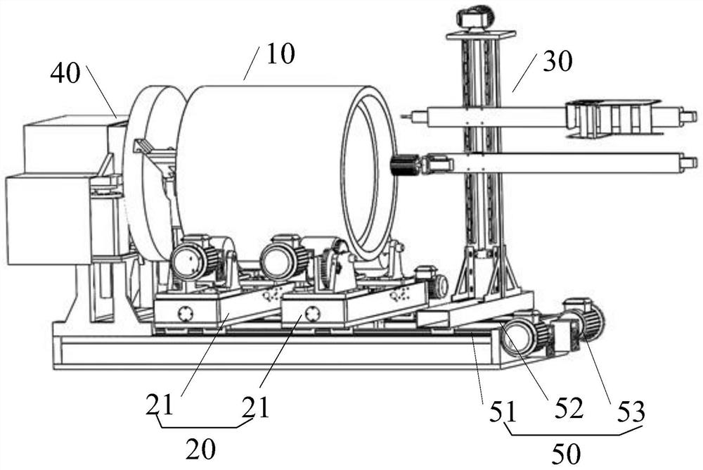
[0039] The specific implementation manner of the present invention will be described in more detail below with reference to schematic diagrams. Advantages and features of the present invention will be apparent from the following description and claims. It should be noted that all the drawings are in a very simplified form and use imprecise scales, and are only used to facilitate and clearly assist the purpose of illustrating the embodiments of the present invention.

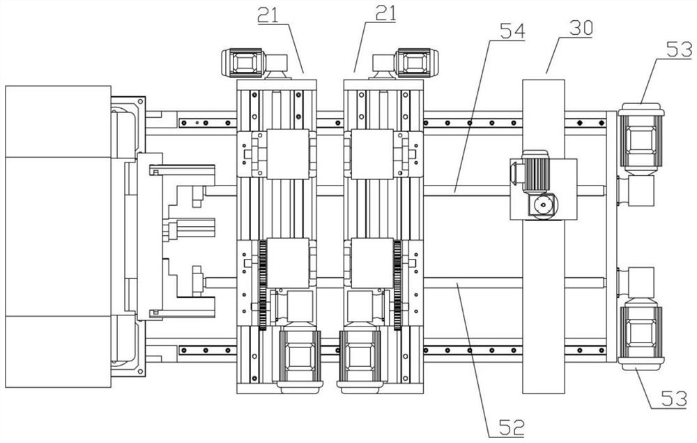
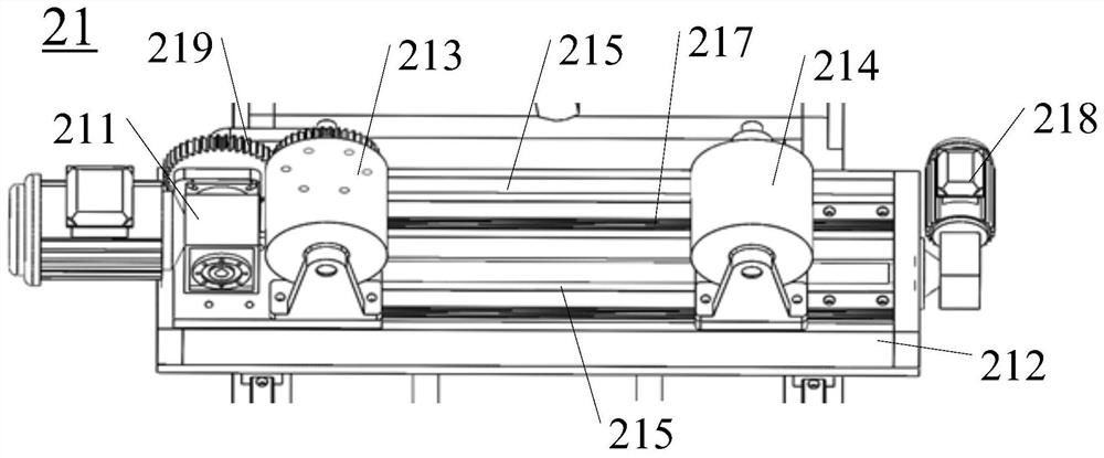
[0040] See eg 1- Figure 5 , this embodiment provides an automatic welding device for a bearing pad 10, which is used for automatic welding of a bearing pad 10 of a sliding bearing, including a support module 50, a guide rail groove module 20 arranged on the support module 50, a chuck clamping Module 40 and welding module 30, the bearing bush 10 is placed on the rail slot module 20, the chuck clamping module 40 is used to clamp the end of the bearing bush 10, and the welding module 30 is used to The inner wall ...


PUM


Abstract

The invention provides an automatic bearing bush welding device and method, which can automatically select a suitable clamping method when the bearing bush has different sizes and specifications; the welding module has two timing belt guide rails, and the welding torch and the wire feeder are fixed on a timing belt At both ends of the guide rail, use the synchronous belt guide rail to adjust the position of the welding process. After the welding is completed, the brush on the other synchronous belt guide rail will scrub the welding position. A pair of guide rail groove modules and welding modules are fixed on the On the support module, the position of the guide rail groove module and the welding module on the support module is adjusted by motor drive to suit the placement of the bearing bush; the chuck clamping module adopts a hydraulic three-jaw chuck, and two screw lifters are used to adjust the hydraulic three-jaw In the working position of the chuck, one side of the bearing bush is fixed with a three-jaw chuck.

Description

technical field [0001] The invention relates to the field of bearing bush processing and production equipment, in particular to an automatic bearing bush welding device and method. Background technique [0002] Sliding bearings are important parts in large machinery. The bearing bush is the part that is in direct contact with the journal during the installation of the sliding bearing. Due to the needs of the working environment of the bearing bush, the friction coefficient of the working surface of the bearing bush is required to be small, and the fatigue strength is sufficient. Good running-in ability and good corrosion resistance. In order to make the bearing work effectively, the addition of the alloy layer on the inner surface of the bearing pad is particularly necessary. [0003] In terms of technology, the traditional method adopts the method of pouring or pressing. The traditional processing method will not only destroy the internal structure of the metal itself, but...

Claims


Application Information

Patent Timeline
Patent Type & Authority Patents(China)
IPC IPC(8): B23K37/02B23K37/053
Inventor 张德义高进可穆开洪万嵘方海峰周健王琪
Owner JIANGSU UNIV OF SCI & TECH IND TECH RES INST OF ZHANGJIAGANG
Learn More