Supporting structure and filter element of filtering structure

A support structure and filter structure technology, applied in semi-permeable membrane separation, chemical instruments and methods, membrane technology, etc., can solve the problems of poor support structure strength, poor filter structure strength, small effective filter area, etc., and achieve negative pressure resistance Good, the porosity is improved, and the effect of increasing the effective filtration area

Pending Publication Date: 2019-05-21
CHENGDU INTERMENT TECH
View PDF12 Cites 1 Cited by
  • Summary
  • Abstract
  • Description
  • Claims
  • Application Information

AI Technical Summary

Problems solved by technology

[0008] The purpose of one aspect of the present invention is to provide a support structure to solve the problems of poor strength and thicker support structures in the prior art
Another object of the present invention is to provide a filter structure and a method for preparing the filter structure, so as to solve the problem of poor filter structure strength in the prior art
The object of another aspect of the present invention is to provide a filter core to solve the problems of poor filter core strength and small effective filter area in the prior art
The purpose of another aspect of the present invention is to provide a sealing structure to solve the problem of poor sealing structure or good sealing effect but complicated structure in the prior art

Method used


Image

  • Supporting structure and filter element of filtering structure
  • Supporting structure and filter element of filtering structure
  • Supporting structure and filter element of filtering structure

Examples


Embodiment 1

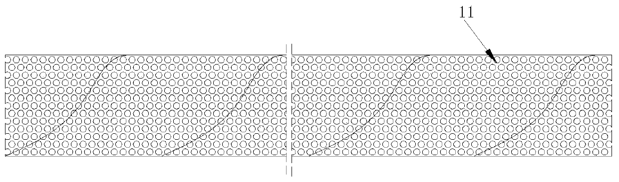
[0177] Such as figure 2 The supporting structure of the shown filter structure includes a support cylinder 1 wound by a strip-shaped coiled material 11, the coiled material 11 has a porous structure, the coiled material 11 is rectangular, and the center of the coiled material 11 The wire is wound in the shape of a cylindrical helix. The thickness of the coiled material 11 is 0.6 mm, and the porosity is 50%. The helix angle α of the helix is ​​75°. The two long sides of the coil 11 are wound and formed by contact welding, and the width of the welding is 3mm. When the helix angle α is 75° and the middle diameter of the support cylinder 1 is 126 mm, the required width of the coil 11 is 102.39 mm.

Embodiment 2

[0179] Such as figure 2 The supporting structure of the shown filter structure includes a support cylinder 1 wound by a strip-shaped coiled material 11, the coiled material 11 has a porous structure, the coiled material 11 is rectangular, and the center of the coiled material 11 The wire is wound in the shape of a cylindrical helix. The thickness of the coiled material 11 is 0.8mm, and the porosity is 70%. The helix angle α of the helix is ​​60°. The two long sides of the coil 11 are wound and formed by contact welding, and the width of the welding is 3mm. When the helix angle α is 60° and the middle diameter of the support cylinder 1 is 126 mm, the required width of the coil 11 is 197.82 mm.

Embodiment 3

[0181] Such as figure 2 The supporting structure of the shown filter structure includes a support cylinder 1 wound by a strip-shaped coiled material 11, the coiled material 11 has a porous structure, the coiled material 11 is rectangular, and the center of the coiled material 11 The wire is wound in the shape of a cylindrical helix. The thickness of the coiled material 11 is 1mm, and the porosity is 80%. The helix angle α of the helix is ​​50°. The two long sides of the coil 11 are wound and formed by contact welding, and the width of the welding is 3 mm. When the helix angle α is 50° and the middle diameter of the support cylinder 1 is 126 mm, the required width of the coil 11 is 254.31 mm.


PUM


Abstract

The invention discloses a supporting structure and filter element of a filtering structure. The supporting structure comprises a supporting cylinder which is formed by winding a strip-shaped coiled material, the coiled material is of a porous structure, and a joint formed by winding the coiled material is not parallel to the central axis of the supporting cylinder. When the supporting cylinder bears internal and external pressure, the maximum principal stress of the supporting cylinder is perpendicular to the central axis and acts on each round section. According to a traditional straight welded pipe (a joint is parallel to the central axis of the welded pipe), the joint directly bears the maximum principal stress, and the requirement of weld joint strength is high. When the joint is not parallel to the central axis of the supporting cylinder, the joint mainly bears component force of the principal stress, namely radial stress and axial stress, the two stress values are obviously smaller than the principal stress of the straight welded pipe, and therefore the thickness of the supporting structure can be obviously reduced at the same work pressure and the same pipe diameter. The porosity can be obviously increased, so that the effect filtering area of the filtering structure is improved.

Description

technical field [0001] The invention relates to the technical field of filter devices, in particular, to a support structure of a filter structure and a filter element. Background technique [0002] The applicant of the present application has submitted publication numbers respectively CN104874798A (named as porous film and its preparation method), CN104874801A (named as porous film and its preparation method), CN104959612A (named as a porous film and its preparation method). film preparation method), CN104959611A (named porous film and porous film preparation method) patent application, discloses a kind of thickness ≤ 1500 micron and foldable flexible metal film, more preferably when the thickness ≤ 200 micron is easy achieve high air permeability. At present, the application of the flexible metal film is mainly used in the filter elements for gas-solid and liquid-solid filtration and separation in harsh environments such as ceramic industry, metallurgy, coal chemical indu...

Claims


Application Information

Patent Timeline
Patent Type & Authority Applications(China)
IPC IPC(8): B01D63/10
CPCB01D63/10B01D63/101
Inventor 高麟汪涛李翔
Owner CHENGDU INTERMENT TECH
Why Eureka
Try Eureka