Method for estimating the remaining useful life of single battery or single batch of battery

A battery and life-span technology, applied in the direction of measuring electricity, measuring electrical variables, measuring devices, etc., to achieve the effect of satisfying operation difficulty, reducing cycle time, and controlling prediction errors

Active Publication Date: 2019-05-21
NANO & ADVANCED MATERIALS INST
View PDF7 Cites 14 Cited by
  • Summary
  • Abstract
  • Description
  • Claims
  • Application Information

AI Technical Summary

Problems solved by technology

All existing methods require a trade-off between predictive accuracy and modeling complexity

Method used


Image

  • Method for estimating the remaining useful life of single battery or single batch of battery
  • Method for estimating the remaining useful life of single battery or single batch of battery
  • Method for estimating the remaining useful life of single battery or single batch of battery

Examples


example 1

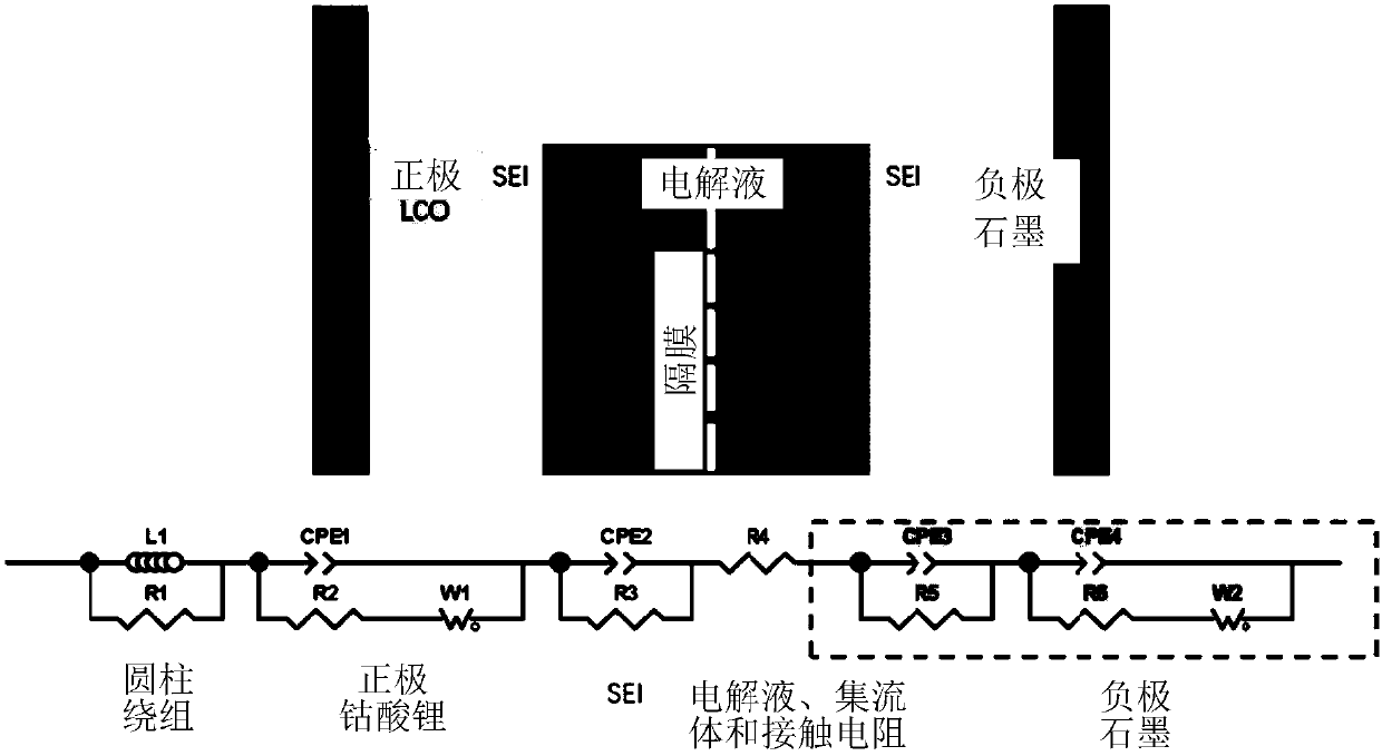
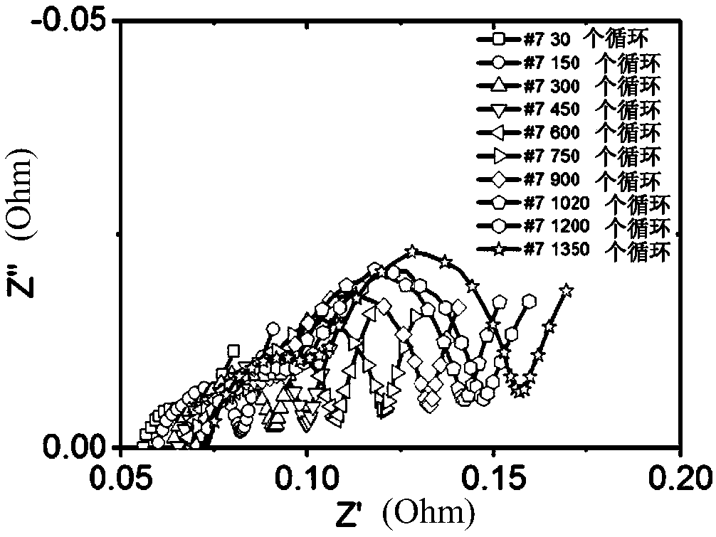
[0108] LiCoO 3 |C system is used as an example to illustrate the life prediction of a single battery. Batteries with similar initial conditions (weight, AC internal resistance, and discharge capacity) were selected for cycling. The room temperature is set at 22°C, the voltage range is 2.75V to 4.35V, and the charge and discharge rates are both 0.5C (1500mA). These batteries are cycled according to the standard operating procedure: first charge the battery to 4.35V with a constant current (1500mA), then continue to charge the battery with this 4.35V as a constant voltage until the current drops to 60mA, and then charge the battery with a constant current (1500mA). The battery is discharged until the voltage of the battery drops to 2.75V. For the 0.5C / 0.5C group, the capacity retention of most cells dropped below 80% after 1000 cycles.

[0109] In the present invention, electrochemical workstation PAR VersaSTAT 3 is used for EIS measurement. Since the internal impedance of t...

example 2

[0121] In this example, change the cathode material to Li(Ni x mn y co z )O 2 (NMC) system for individual battery life prediction. Batteries with similar initial conditions (weight, AC internal resistance, and discharge capacity) were screened for cycling. In this example, the room temperature is set to 22°C. Of course, the temperature can also be increased to speed up the experiment if acceleration is required, for example, to 30°C, 40°C, etc. The experimental voltage range was 2.75V to 4.2V. The charge and discharge rates are both 0.5C (1300mA). The shielded battery was cycled according to standard operating procedure: first charged to 4.2V with constant current (1300mA), further charged with constant voltage until the current dropped to 60mA, and then discharged with constant current (1300mA) until the voltage reached 2.75V . For the 0.5C / 0.5C group, the capacity retention of most batteries dropped below 80% after 400 cycles.

[0122] According to the present invent...

example 3

[0135] In this example, an accelerated cycle test is used to determine the average life of a batch of batteries. Accelerated experiments were designed by discharge rate (1C discharge rate and 2C discharge rate). Two sets of cells were obtained from the same manufacturing process and screening process. The two groups of batteries were cycled at different discharge rates of 1C and 2C, respectively. Each battery selected for testing can be predicted by the single battery prediction method through 300 cycles. The life of each tested battery of the two groups of batteries measured by the method of measuring a single battery described above has been listed in Table 5, wherein the first four batteries are marked as #111, #113, #114 and The #115 cell was used for the 1C cycle and the last four cells, namely the cells labeled #119, #120, #122 and #228 were used for the 2C cycle. Two examples of typical forecasts are Figure 8A and 8B Shown, which respectively represent the relatio...


PUM


Abstract

The present invention relates to a method for estimating the remaining useful life of a battery, comprising the steps of: providing a single battery; performing multiple charging-discharging cycles ona single battery; performing measurement of electrochemical impedance spectroscopy on the single battery during at least a part of the charging-discharging cycles, and obtaining charge transfer resistance and surface layer resistance of the single battery through the fitting of an equivalent circuit model; establishing the relationship between the capacity of a single battery and the cycling times by means of the charge transfer resistance and the surface layer resistance and capacity obtained by multiple cycles; predicting the remaining battery capacity or the number of remaining cycles of the battery by means of the already-established relationship between the capacity and the cycling times. The present invention also proposes a method for estimating the remaining useful life of a batchof batteries.

Description

technical field [0001] The present invention relates to the field of battery life prediction, and more particularly, to a method for estimating the remaining service life of a single battery or a single batch of batteries. Background technique [0002] Lithium-ion batteries (LIBs) are currently widely used to power new consumer devices and functional tools, such as battery-powered electric / hybrid vehicles (EV / HEV), as well as temporary storage systems for renewable energy. However, the performance of lithium-ion batteries degrades over time due to aging, environmental influences, and dynamic loads. Therefore, it is necessary to understand the battery aging behavior in vehicle applications, monitor the battery health, predict the battery's remaining useful life (RUL), take measures to slow down the degradation, and ultimately avoid unexpected catastrophic failures. In practical applications, accurate estimation of battery state-of-health (SOH) and lifetime plays an important...

Claims


Application Information

Patent Timeline
Patent Type & Authority Applications(China)
IPC IPC(8): G01R31/392G01R31/367
Inventor 舒时伟周颖瑜辛见卓何国强
Owner NANO & ADVANCED MATERIALS INST
Why Eureka
Try Eureka