Quick transient response LDO (Low Drop Out) voltage stabilizer circuit based on inverter
A transient response and inverter technology, applied in the circuit field, can solve the problems of large quiescent current, unfavorable energy saving, etc., achieve reliable performance, and improve the effect of transient response speed
- Summary
- Abstract
- Description
- Claims
- Application Information
AI Technical Summary
Problems solved by technology
Method used
Image
Examples
Embodiment 1
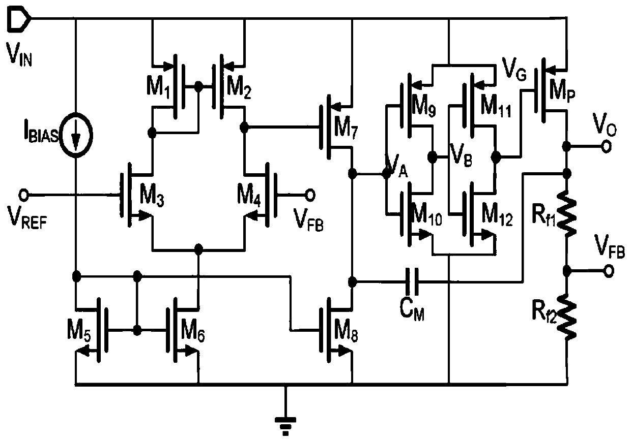
[0035] A novel inverter-based fast transient response LDO voltage regulator circuit design in this embodiment can significantly improve the transient response capability of the LDO without increasing the quiescent current. The invention adopts TSMC 65nm technology for simulation verification, the input voltage range is: 0.7-0.9V, the output voltage is 0.5V, the load capacitance is 1-10pF, and the load current is 1-100mA.
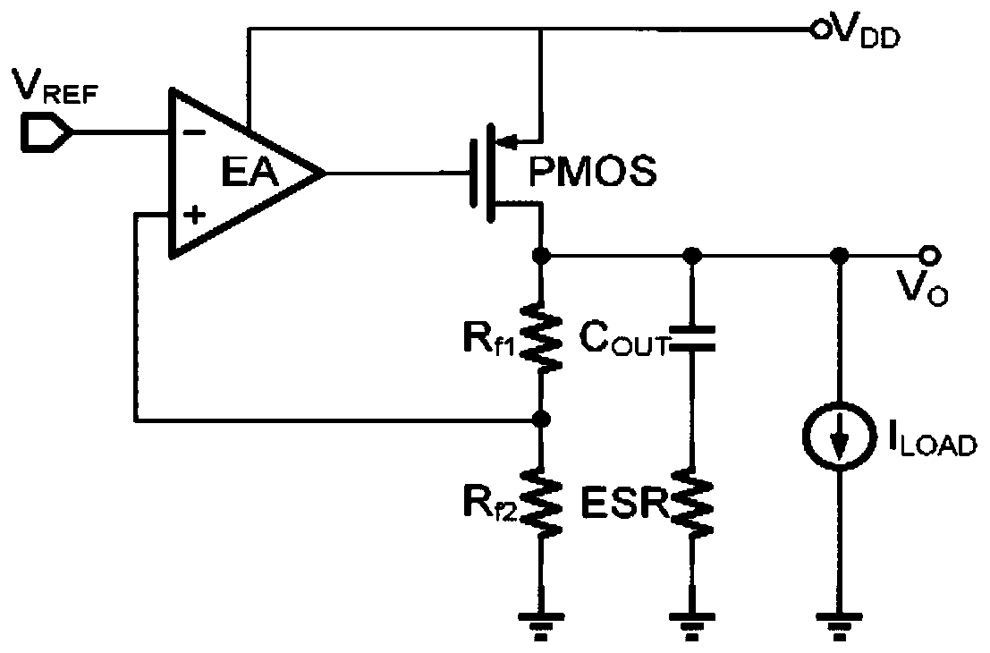
[0036] Such as figure 2 Shown is a schematic circuit diagram of a typical LDO regulator, which consists of an error amplifier EA, a PMOS power transistor, a negative feedback network and an output capacitor C OUT and its equivalent series resistance ESR. The feedback network detects changes in the output voltage and feeds this change back to the positive input of the EA, which then amplifies this input voltage and the reference voltage V REF the difference between. The output voltage of the error amplifier EA changes the voltage at the gate of the PMOS p...
PUM
 Abstract
Description
Claims
Application Information
 - R&D
- Intellectual Property
- Life Sciences
- Materials
- Tech Scout
- Unparalleled Data Quality
- Higher Quality Content
- 60% Fewer Hallucinations
Browse by: Latest US Patents, China's latest patents, Technical Efficacy Thesaurus, Application Domain, Technology Topic, Popular Technical Reports.
© 2025 PatSnap. All rights reserved.Legal|Privacy policy|Modern Slavery Act Transparency Statement|Sitemap|About US| Contact US: help@patsnap.com


