Current collector with solid electrolyte interface phase and production method
A technology of solid electrolyte and current collector, applied in the field of electrochemistry, can solve the problems of ignoring the construction of high-quality SEI film, the cycle conversion of lithium anode and the coulombic efficiency that need to be improved urgently, and the inability to fully utilize the high specific surface and internal space of the three-dimensional current collector. To achieve the effect of maintaining cycle stability, superior electrochemical performance, and inhibited growth
- Summary
- Abstract
- Description
- Claims
- Application Information
AI Technical Summary
Problems solved by technology
Method used
Image
Examples
Embodiment 1
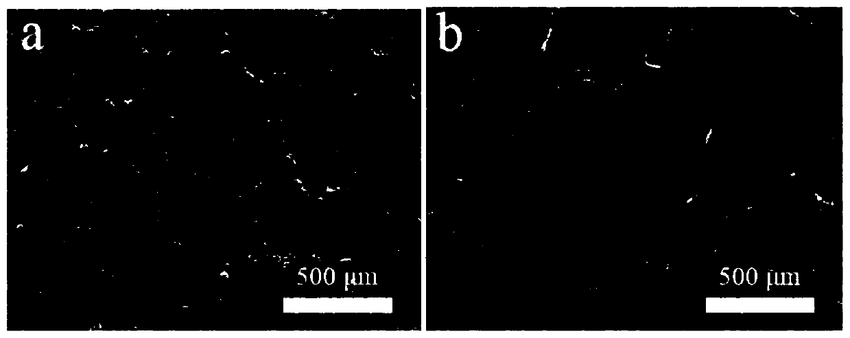
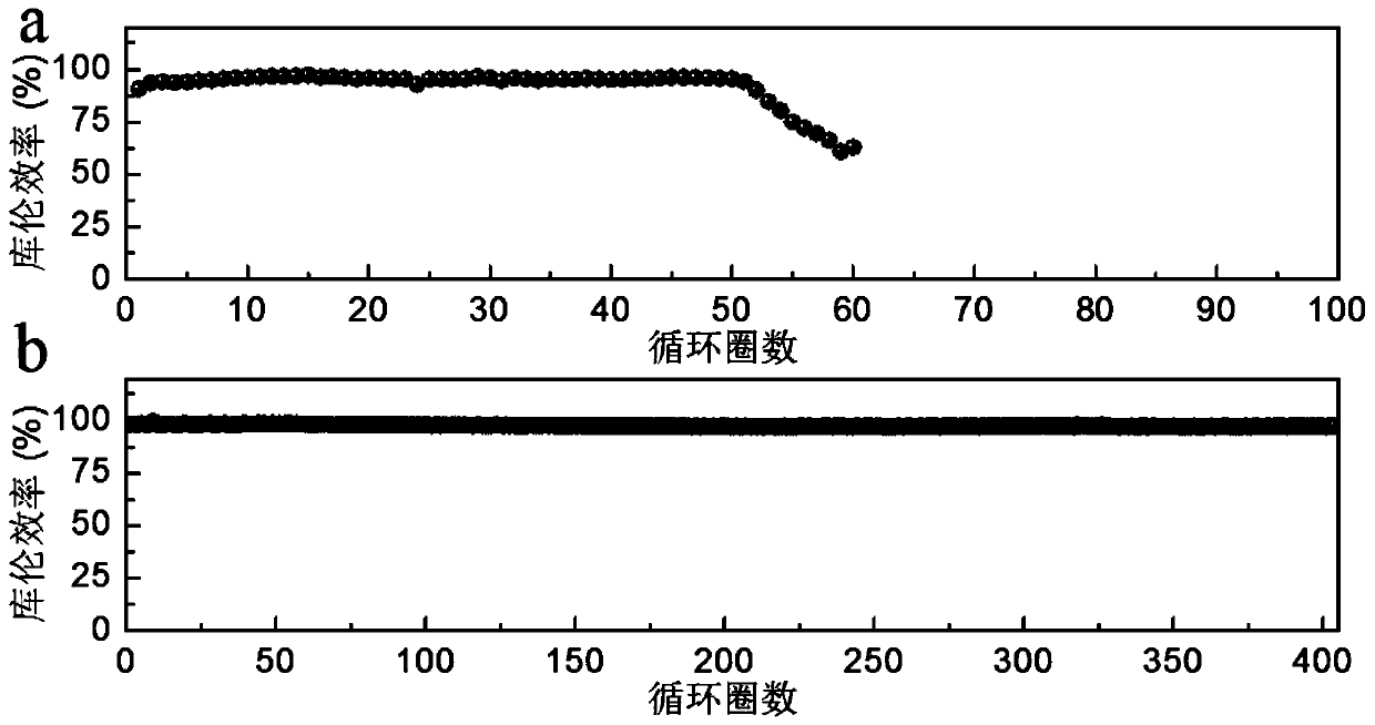
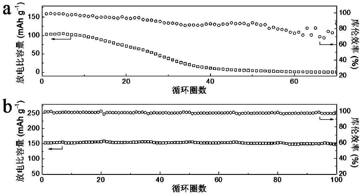
[0032] Sacrifice a thin lithium layer on the current collector to build a solid electrolyte interface phase as follows:
[0033] 1) Introduce a sacrificial lithium thin layer: put a current collector and a metal lithium sheet in the electrolytic cell as the working electrode and counter electrode respectively; inject electrolyte into the electrolytic cell, and apply -0.2V~-0.05V cathode potential or -2mA to the working electrode / cm 2 ~-0.05mA / cm 2 Cathodic current, so that lithium is electrodeposited on the working electrode to obtain a sacrificial lithium thin layer with a thickness of 5 μm to 30 μm; or heat metal lithium to melt it, immerse the current collector in it for a period of time, take it out and cool it to room temperature, and obtain a thin layer of sacrificial lithium with a thickness of 5 μm to 30 μm. 30μm sacrificial lithium thin layer;
[0034] 2) Build solid electrolyte interface phase: After step 1) is completed, apply 0.2V to 2.0V anode potential or 100m...
Embodiment 2
[0037] The difference between this example and Example 1 is that in step 1), copper mesh is used as the working electrode, and a cathode potential of -0.2V is applied to the working electrode, so that lithium is electrodeposited on the working electrode, and a sacrificial lithium thin layer with a thickness of 5 μm is obtained. Others are the same as in Example 1.
Embodiment 3
[0039] The difference between this example and Example 1 is that in step 1), the copper mesh is used as the working electrode, and a cathode potential of -0.05V is applied to the working electrode, so that lithium is electrodeposited on the working electrode, and a sacrificial lithium thin layer with a thickness of 30 μm is obtained. Others are the same as in Example 1.
PUM
| Property | Measurement | Unit |
|---|---|---|
| thickness | aaaaa | aaaaa |
| thickness | aaaaa | aaaaa |
| thickness | aaaaa | aaaaa |
Abstract
Description
Claims
Application Information
 - R&D
- Intellectual Property
- Life Sciences
- Materials
- Tech Scout
- Unparalleled Data Quality
- Higher Quality Content
- 60% Fewer Hallucinations
Browse by: Latest US Patents, China's latest patents, Technical Efficacy Thesaurus, Application Domain, Technology Topic, Popular Technical Reports.
© 2025 PatSnap. All rights reserved.Legal|Privacy policy|Modern Slavery Act Transparency Statement|Sitemap|About US| Contact US: help@patsnap.com


