Method for improving running stability of fuel cell
A fuel cell and stability technology, used in fuel cells, circuits, electrical components, etc., can solve the problems of doping acid loss and performance degradation, and achieve the effect of slowing performance degradation, reducing loss and prolonging battery life.
- Summary
- Abstract
- Description
- Claims
- Application Information
AI Technical Summary
Problems solved by technology
Method used
Image
Examples
Embodiment 1
[0021] (1) Preparation of gas diffusion electrodes
[0022] The size of the prepared gas diffusion electrode is 2.3cm×2.3cm. The gas diffusion backing is Toray TGP-H-90 carbon paper. The carbon powder used in the microporous layer is VulcanXC-72R, the adhesive used is polytetrafluoroethylene (PTFE), and the contents of carbon powder and PTFE are 85wt.% and 15wt.%. The catalyst used in the catalytic layer is 45.7wt.%Pt / C (Tanaka Kikinzoku KogyoCo., Ltd.), and the Pt loading is 1.0mg cm -2 , the catalytic layer binder is PTFE, and the percentage in the catalytic layer is 30wt.%.
[0023] (2) Preparation of Membrane Electrode Assembly
[0024] The electrolyte membrane is a phosphoric acid-doped ABPBI membrane with a size of 4cm×4cm and a phosphoric acid doping amount of 370wt.%. In the membrane electrode hot-pressing mold, place two prepared identical gas diffusion electrodes on both sides of the electrolyte membrane, put the mold into a hot-pressing machine at 140°C for 5 mi...
Embodiment 2
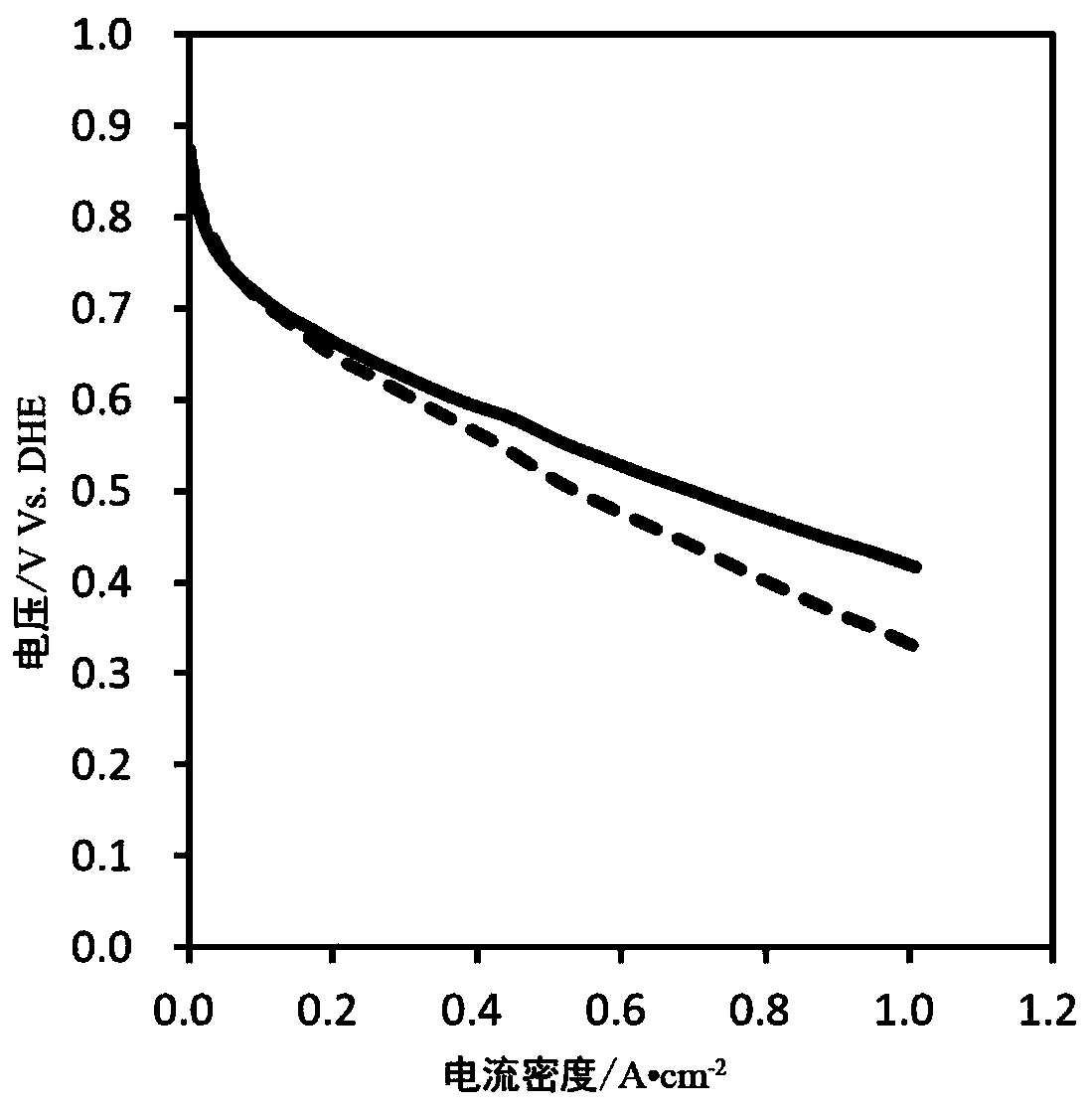
[0028] Single cell at 0.2A·cm -2 Run at low current density for 160s, followed by 0.8A·cm -2 Run at high current density for 224 s, so that the average operating current is 0.55A cm -2 , the rest of the steps are the same as in Example 1. The discharge performance curve results are as follows figure 2 shown. Battery at 0.55A·cm -2 Under the current density, the voltage decreases by 0.09V before and after operation, and the membrane resistance increases by 0.03Ω·cm 2 .
Embodiment 3
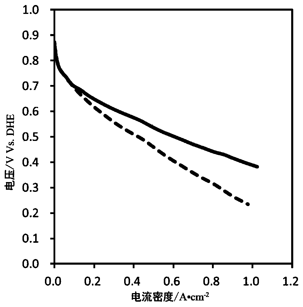
[0030] Single cell at 0.55A·cm -2 Run 500h under the current density, and the remaining steps are the same as in Example 1. The discharge performance curve results are as follows image 3 shown. Battery at 0.55A·cm -2 Under the current density, the voltage decreases by 0.17V before and after operation, and the membrane resistance increases by 0.1 Ω cm 2 .
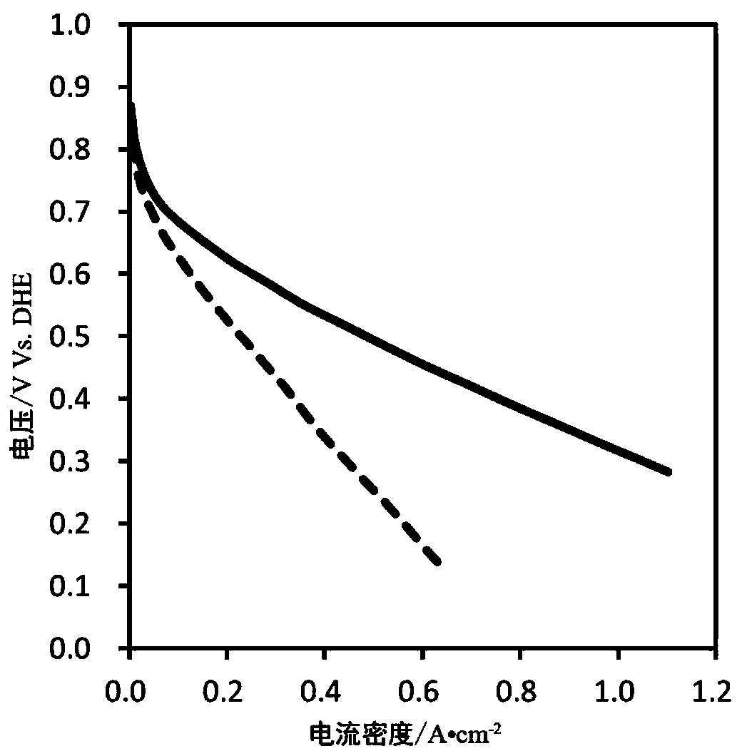
[0031] As can be seen from the above-mentioned Example 1, Example 2 and Example 3, the average current density is 0.55A cm -2 Under the condition of , the embodiment 2 with the longest running time at low current density has the smallest voltage drop and the smallest increase in membrane resistance after 500h, indicating that the loss of phosphoric acid is the least and the performance decay is the smallest. Therefore, the present invention adopts the method of alternately operating under high and low current densities, which can effectively slow down the performance degradation of the battery and significantly prolong...
PUM
| Property | Measurement | Unit |
|---|---|---|
| current density | aaaaa | aaaaa |
| current density | aaaaa | aaaaa |
Abstract
Description
Claims
Application Information
 - R&D
- Intellectual Property
- Life Sciences
- Materials
- Tech Scout
- Unparalleled Data Quality
- Higher Quality Content
- 60% Fewer Hallucinations
Browse by: Latest US Patents, China's latest patents, Technical Efficacy Thesaurus, Application Domain, Technology Topic, Popular Technical Reports.
© 2025 PatSnap. All rights reserved.Legal|Privacy policy|Modern Slavery Act Transparency Statement|Sitemap|About US| Contact US: help@patsnap.com


