Heat Exchangers and Air Conditioning Units

A heat exchanger and space technology, applied in heat exchange equipment, air conditioning systems, indirect heat exchangers, etc., can solve the problems of small superheat, damage balance, large superheat, etc. frost effect

Active Publication Date: 2020-05-08
DAIKIN IND LTD
View PDF11 Cites 0 Cited by
  • Summary
  • Abstract
  • Description
  • Claims
  • Application Information

AI Technical Summary

Problems solved by technology

[0003] For example, according to the heat exchanger described in Patent Document 1 (Japanese Unexamined Patent Application Publication No. 2005-201491) and the heat exchanger described in Patent Document 2 (Japanese Patent Application Publication No. 2005-127597), the following heat exchanger is disclosed : The problem is that since heat exchange is preferentially performed on the windward side in the direction of air flow, the superheat degree is large on the windward side and small on the leeward side, thus breaking the balance

Method used


Image

  • Heat Exchangers and Air Conditioning Units
  • Heat Exchangers and Air Conditioning Units
  • Heat Exchangers and Air Conditioning Units

Examples


Embodiment Construction

[0068] (1) Overall structure of the air conditioner 1

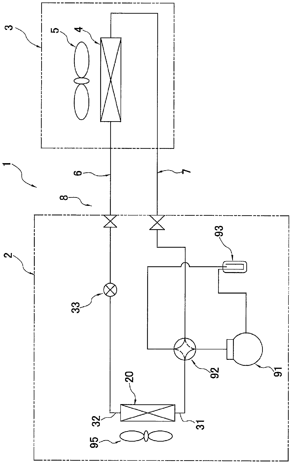
[0069] figure 1 It is a schematic circuit diagram showing the structure of the refrigeration apparatus 1 which concerns on one Embodiment of this invention.

[0070] The air conditioner 1 is a device used for cooling and heating in a building in which an air conditioner indoor unit 3 is installed by performing a vapor compression refrigeration cycle operation. The air-conditioning indoor unit 3 is configured by connecting refrigerant communication pipes 6 and 7 .

[0071] The air-conditioning outdoor unit 2, the air-conditioning indoor unit 3 and the refrigerant communication pipes 6 and 7 are connected to form a refrigerant circuit 8. The refrigerant circuit 8 is composed of a compressor 91, a four-way switching valve 92, an outdoor heat exchanger 20, an expansion The valve 33, the indoor heat exchanger 4, the gas-liquid separator 93, and the like are connected by refrigerant piping. Refrigerant is sealed in the refri...


PUM


Abstract

Provided are a heat exchanger and an air-conditioning apparatus capable of separating refrigerant flowing on the windward side of the flat porous tube and the air conditioner while suppressing the difference in compressive strength between the windward side and the leeward side of the flat porous tube to be small. The difference in the state of the refrigerant flowing on the leeward side is suppressed to be small. An outdoor heat exchanger (20), the outdoor heat exchanger (20) has: a plurality of flat porous tubes (50); a return header (24); a plurality of heat transfer fins (40); and a partition member ( 70), which is provided with a porous side concavo-convex portion (88a) on the leeward side, wherein the space (61a, 61b) connecting the flat porous pipe (50) inside the folded header (24) is configured such that the air flow direction More refrigerant flows through the windward side than the downwind side.

Description

technical field [0001] The present invention relates to heat exchangers and air conditioners. Background technique [0002] Conventionally, there is known a heat exchanger that includes a plurality of flat porous tubes, fins joined to the plurality of flat porous tubes, and headers connected to ends of the plurality of flat porous tubes. The refrigerant flowing inside the flat porous tube exchanges heat with the air flowing outside the flat porous tube. [0003] For example, according to the heat exchanger described in Patent Document 1 (Japanese Unexamined Patent Application Publication No. 2005-201491) and the heat exchanger described in Patent Document 2 (Japanese Patent Application Publication No. 2005-127597), the following heat exchanger is disclosed : The problem is that since the heat exchange is preferentially performed on the windward side in the air flow direction, the degree of superheat is large on the windward side and small on the downwind side, thereby break...

Claims


Application Information

Patent Timeline
Patent Type & Authority Patents(China)
IPC IPC(8): F28F9/02F25B39/00F28F1/02F28D1/053
CPCF25B39/00F28F9/0204F28F9/0224F24F1/18F28D1/05391F28F1/32F28D2021/0068F28F9/0263F28F9/0268F28F9/0282F28D1/05325
Inventor 井上智嗣坂卷智彦山口智也佐藤健山田甲树神藤正宪织谷好男
Owner DAIKIN IND LTD
Why Eureka
Try Eureka