Robot rapid positioning method for curved surface components

A robot and surface technology, applied in the field of robotics, can solve the problems of large environmental impact and low monocular vision positioning accuracy, and achieve the effects of simple system, improved work efficiency and reliability, and accurate reconstruction.

Active Publication Date: 2019-05-24
NANJING UNIV OF AERONAUTICS & ASTRONAUTICS
View PDF5 Cites 16 Cited by
  • Summary
  • Abstract
  • Description
  • Claims
  • Application Information

AI Technical Summary

Problems solved by technology

[0004] The purpose of the present invention is to solve the problem that the positioning accuracy of existing robots using monocular vision is not high, and the use of structured light scanning positioning is greatly affected by the environment, and to invent a robot facing curved surface components that has high positioning accuracy and is not affected by the environment Binocular Vision Positioning Method

Method used


Image

  • Robot rapid positioning method for curved surface components
  • Robot rapid positioning method for curved surface components
  • Robot rapid positioning method for curved surface components

Examples


Embodiment Construction

[0039] The present invention will be described in further detail below in conjunction with the accompanying drawings.

[0040] Such as Figure 1-7 as shown,

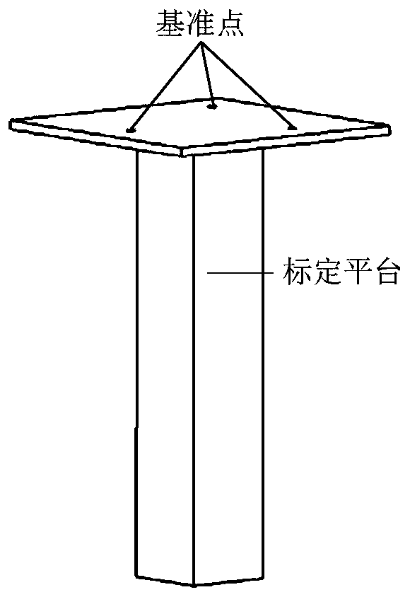
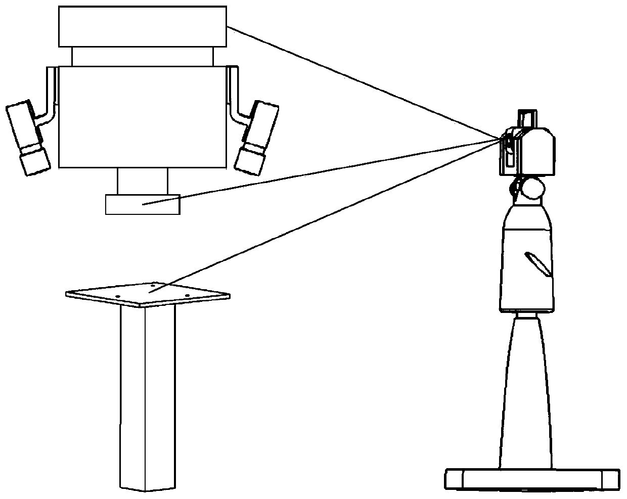
[0041] The robot visual positioning system involved in the present invention includes a robot, an end effector 3, and a visual measurement system 2. The end effector 2 is connected to the robot through a robot flange 1, and the visual measurement system 2 is installed on the end effector 3; before positioning, the robot The position of the curved surface component is random, and it is necessary to ensure that the curved surface component is within the reach of the robot; in the present invention, the positioning completion state is specified when the end effector tool reaches the centroid of the curved surface component or a certain distance above the centroid, such as Figure 7 shown.

[0042] Robot positioning process of the present invention is as Figure 6 As shown, it includes the following steps.

[0043] Step ...


PUM


Abstract

The invention relates to a robot rapid positioning method for curved surface components. The robot rapid positioning method is characterized by comprising the following steps that (1) a conversion model between a robot flange, an end effector and a coordinate system of a vision measuring system is established by measuring reference points through a laser tracker to obtain calibration parameters; (2) triangular auxiliary reflecting targets are stuck at the corner points of the curved surface components, images of the curved surface components are acquired by the vision measuring system, two-dimensional pixel point coordinates of the auxiliary reflecting targets are extracted, and three-dimensional coordinates of the reflecting targets in the coordinate system of the vision measuring systemare calculated; and (3) the current pose parameters of a robot are calculated according to the visual measurement coordinates and calibration parameters of the curved surface components, and the motion amount of the robot is calculated by comparing with a target pose. The robot rapid positioning method improves the reliability of hand-eye calibrated parameters; positioning of information for the curved surface components is fast and accurate; and the robot rapid positioning method can be widely used for rapid positioning of the aviation and automobile curved surface parts and the like.

Description

technical field [0001] The invention relates to a robot technology, in particular to a robot positioning technology, in particular to a fast robot positioning method for curved surface components. Background technique [0002] Industrial robots have been widely used in the automotive and electronics industries, but most of them use offline programming to control the robot's pose, and cannot locate the target by active identification and positioning, so the scope of use is extremely limited; and in military fields such as aerospace, due to its With the characteristics of special working environment and complex object features, the application range of robot vision is narrow. At present, high-end and intelligentization are becoming research hotspots in the field of industrial robots, and the positioning of industrial robots assisted by machine vision has a very broad application prospect in the field of aerospace. [0003] There have been some research results in the field of...

Claims


Application Information

Patent Timeline
Patent Type & Authority Applications(China)
IPC IPC(8): B25J19/00G01B11/00
Inventor 黄翔李泷杲李根
Owner NANJING UNIV OF AERONAUTICS & ASTRONAUTICS
Why Eureka
Try Eureka