
Multifunctional shield synchronous grouting model test apparatus

A model test device, synchronous grouting technology, applied in vertical shaft equipment, shaft lining, mining equipment, etc., can solve problems such as single

Inactive Publication Date: 2019-05-24
GUANGZHOU UNIVERSITY
View PDF5 Cites 11 Cited by
  • Summary
  • Abstract
  • Description
  • Claims
  • Application Information

AI Technical Summary

Problems solved by technology

[0003] Theoretical methods for tunnel construction at home and abroad are mainly empirical methods, analytical solution methods, and test methods. The test methods include engineering scales and indoor scales. Because engineering scales have high cost requirements and cannot be reused, research on indoor scales has attracted much attention. Attention and use, the scale test has a certain repeatability, the cost is lower than the field test, and can add a variety of conditions that cannot be realized in the field test according to the research problem, and the synchronous grouting is the most critical for the entire shield tunnel construction As one of the links, the current research issues in the patents of synchronous grouting model tests for tunnel construction are relatively simple, basically all are the disturbance effects on the surrounding soil and the segment compression analysis under different grouting environments, and there is no systematic , Comprehensive simulation of a series of variable factors that exist in the entire tunnel excavation process

Method used


Image

  • Multifunctional shield synchronous grouting model test apparatus
  • Multifunctional shield synchronous grouting model test apparatus
  • Multifunctional shield synchronous grouting model test apparatus

Examples


Embodiment Construction

[0024] The present invention will be further described in detail in conjunction with the accompanying drawings and specific embodiments.

[0025] In order to facilitate a unified review of the various reference signs in the drawings of the specification, the unified description of the reference signs appearing in the drawings of the specification is as follows:

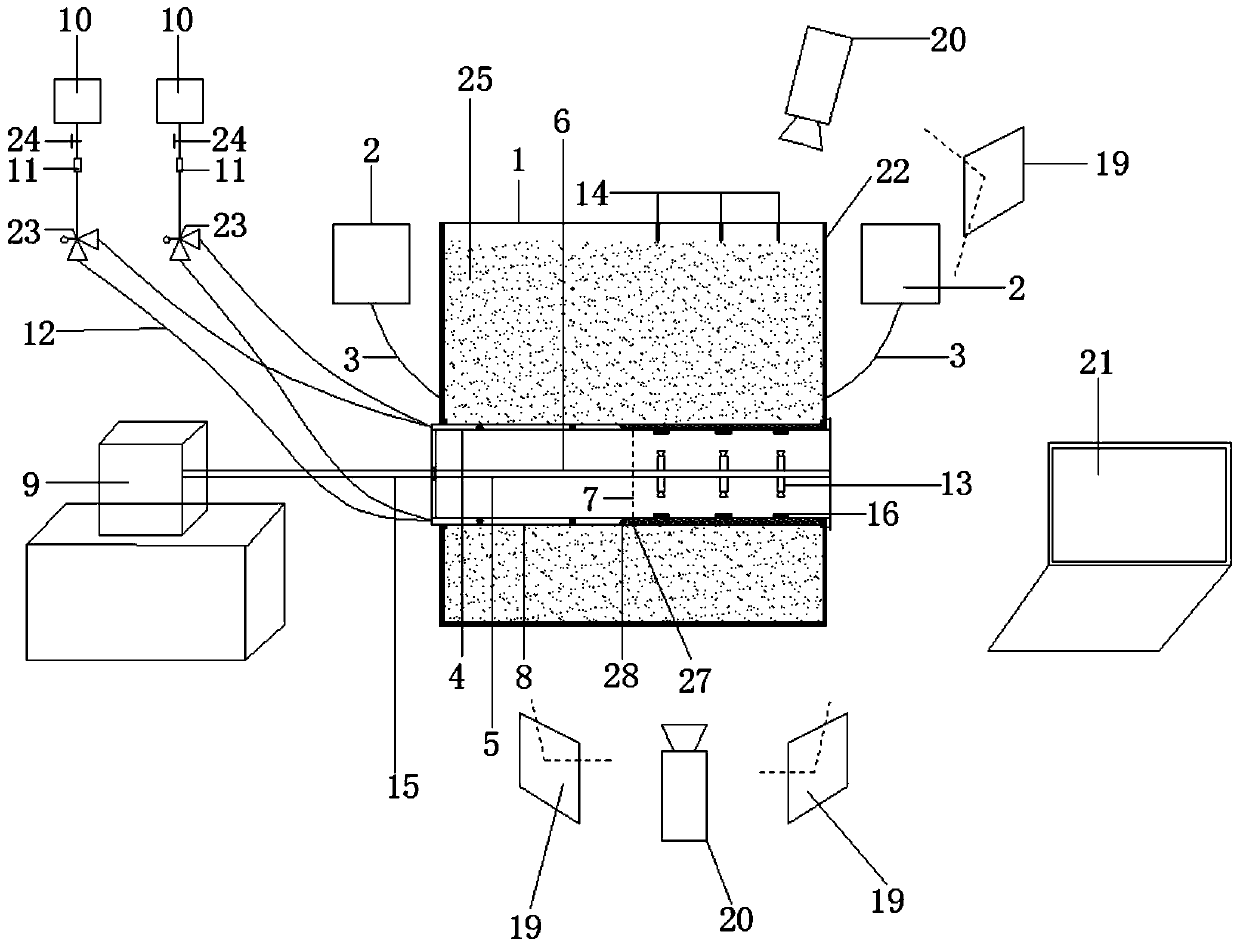
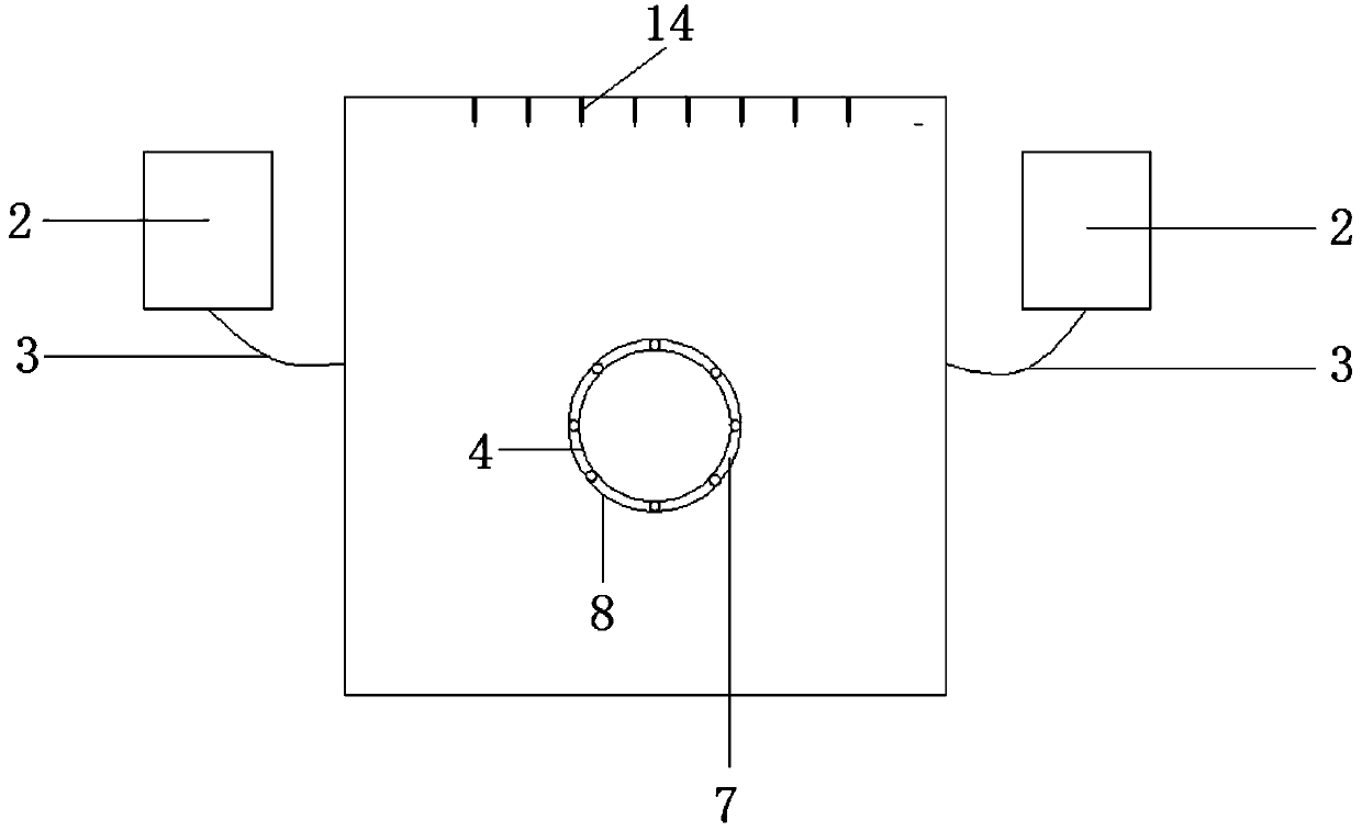
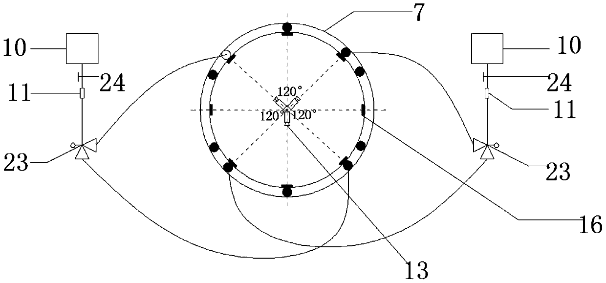
[0026] Transparent soil box 1; water tank 2; water guide pipe 3; simulated segment 4; fixed rod 5; push rod 6; grouting ring piece 7; simulated shield tail 8; propulsion hydraulic cylinder 9; 11; grouting pipeline 12 grouting pipeline; high-definition wide-angle camera 13; displacement sensor 14; moving rod 15; grouting pressure sensor 16; pore water pressure sensor 17; earth pressure sensor 18; laser 19; high-precision camera 20; Computer 21; organic transparent glass plate 22; three-way flow valve 23; control valve 24; transparent soil 25; ball 26; shield tail brush 27;

[0027] combine figure 1 , figure 2As sho...


PUM


Abstract

The invention relates to a multifunctional shield synchronous grouting model test apparatus, comprising a transaprent soil box, a simulation shield tail inserted into the transparent soil box, a simulation segment inserted into the simulation shield tail, transaprent soil, a grouting system with a plurality of grouting pipelines, a grouting ring sleeving the simulation segment, a propelling systemwith a propelling bar, and a plurality of cameras. The two ends of the simulation segment are in contact with the inner wall of the transaprent soil box or exposed out of the transaprent soil box; one end of the simulation shield tail is exposed out of the transparent soil box; a circular space is reserved between the simulation shield tail and the simulation segment; the grouting ring is positioned in the circular space; the grouting pipelines are connected to grouting holes; every two adjacent grouting holes spray grouts different in color; the simulation shield tail is fixedly connected with the propelling bar; the cameras are arranged on the periphery of the propelling bar. The multifunctional shield synchronous grouting model test apparatus is suitable for simulating a grouting process under underground water directional seepage and precisely analyzing a grout diffusion process, and is within the technical field of shield synchronous grouting model test platforms.

Description

technical field [0001] The invention relates to a shield machine synchronous grouting model test platform, in particular to a multifunctional shield machine synchronous grouting model test device. Background technique [0002] With the rapid advancement of urbanization, the contradiction between urban traffic construction and dense buildings has gradually become prominent. In order to solve this contradiction, more and more cities are focusing on the development of underground space, among which underground tunnels are gradually being used by major The city makes full use of it. Among the many tunnel construction methods, the shield method has gradually become the mainstream construction method of underground engineering after more than one hundred years of development. Compared with the traditional shield construction method, the shield method has its unique construction advantages. The main advantages are that it does not affect ground traffic and residents' lives, and the...

Claims


Application Information

Patent Timeline
IPC IPC(8): E21D11/10E21D9/06
Inventor 刘超高守栋刘海崔杰
Owner GUANGZHOU UNIVERSITY
Learn More