Acoustic device and electronic equipment

An acoustic device and sound wave technology, applied in the field of acoustics, can solve the problems of poor low-frequency effect of the acoustic system, volume limitation of passive radiators, and small sound volume of passive radiators, etc., and achieve the effects of improving sensitivity, improving low-frequency sensitivity, and improving low-frequency effects

Active Publication Date: 2019-05-24
GOERTEK INC
View PDF11 Cites 38 Cited by
  • Summary
  • Abstract
  • Description
  • Claims
  • Application Information

AI Technical Summary

Problems solved by technology

[0006] The main purpose of the present invention is to provide a sound generating device and electronic equipment, aiming to solve the problem that the volume of the passive radiator is limited, resulting in a small sound volume of the passive radiator, so that the low-frequency effect of the acoustic system is poor

Method used


Image

  • Acoustic device and electronic equipment
  • Acoustic device and electronic equipment
  • Acoustic device and electronic equipment

Examples


Embodiment 1

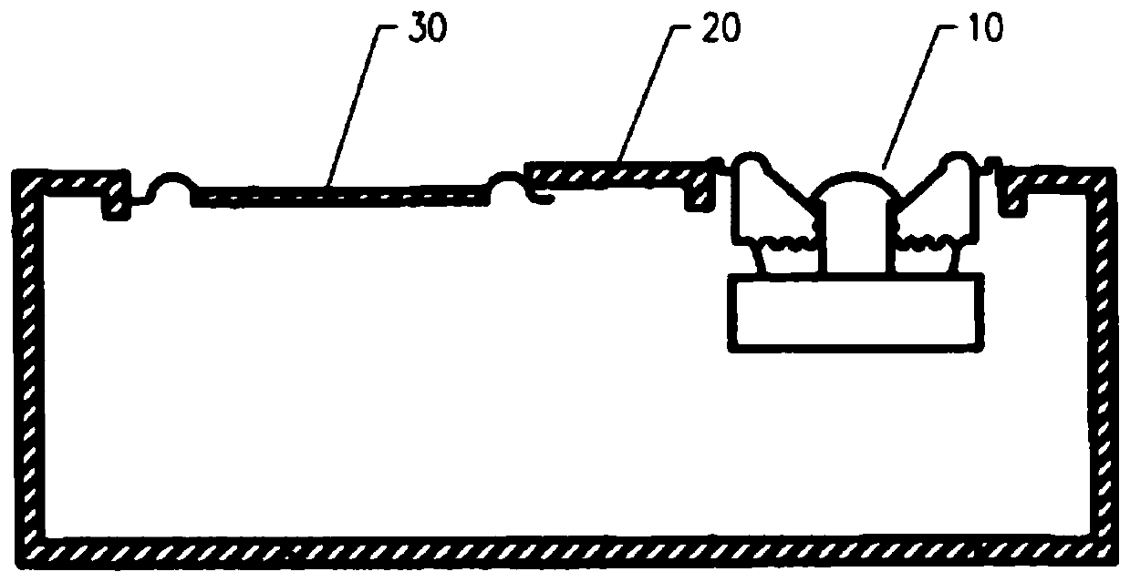
[0051] Such as Figure 4 As shown, an acoustic device includes a sound emitting unit 1. In this embodiment, the sound emitting unit 1 is a miniature sound emitting unit, and more specifically, the sound emitting unit 1 is a miniature moving coil speaker. The sound unit 1 generally includes a housing and a vibration system and a magnetic circuit system fixed in the housing. The vibration system includes a vibration diaphragm 11 fixed on the housing and a voice coil combined with the vibration diaphragm 11. The magnetic circuit system is formed with A magnetic gap, the voice coil is arranged in the magnetic gap, and the voice coil reciprocates up and down in the magnetic field after the alternating current is applied, thereby driving the vibrating diaphragm 11 to vibrate and produce sound. Of course, in other embodiments, the sound generating unit 1 can also be other types of micro speakers, which will not be repeated here.

[0052] The acoustic device is provided with a sound outl...

Embodiment 2

[0090] Such as Picture 10 As shown, the main difference between this embodiment and the first embodiment is that the flexible deformable part 22 in this embodiment is an independent mounting part, and a mounting hole 5 (combined with Image 6 (Shown), the flexible deformable portion 22 is mounted on the mounting hole 5. Specifically, the flexible deformable portion 22 is fixedly connected to the first housing part around the mounting hole 5 by bonding, welding or hot melt. This improved design makes the selection of the flexible deformable part 22 more convenient, and can achieve a more realistic combination with the first housing. At the same time, a through hole is provided on the first shell, which can simplify the product process. Here, the flexible deformation portion 22 is a flat plate structure. And when the flexible deformation part 22 is a wave-shaped structure (combined Picture 11 As shown), the flexible deformable portion 22 and the first housing part around the mo...

Embodiment 3

[0092] The main difference between this embodiment and the above embodiments is that the acoustic device in this embodiment is provided with a sound channel, which is designed corresponding to the sound outlet 4, and the sound waves on the front side of the vibrating diaphragm 11 are radiated to the sound channel through the sound channel. Speak out 4. This design is more in line with the design requirements of some terminal products, does not occupy the space of the panel of mobile phones and other panels, is conducive to the design of full screens, and at the same time avoids occlusion and interference from other components.

[0093] Specific, such as Picture 12 As shown, the sound unit 1 is installed in the first housing 2 and the sound channel is also provided on the first housing 2. In other embodiments, it is also possible that the sound channel is provided on the second housing 3, and the sound component is docked with the sound channel; or the sound channel is separately...


PUM


Abstract

The embodiment of the invention provides an acoustic device and electronic equipment, the acoustic device comprises a first closed cavity and a second closed cavity, a spacing part can be at least partially and flexibly deformed, the first closed cavity is adjacent to a vibrating diaphragm, and the second closed cavity is far away from the vibrating diaphragm; When the vibrating diaphragm vibrates, the internal sound pressure of the first closed cavity is changed, the flexible deformation part is deformed along with the change of the sound pressure in the first closed cavity, and the volume ofthe first closed cavity is flexibly adjusted; The second sealed cavity seals sound waves generated when the flexible deformation part deforms in the second sealed cavity, and the flexible deformationpart is of a single-layer structure made of a thermoplastic elastomer material layer or a multi-layer composite structure at least compounded with a thermoplastic elastomer material layer. Therefore,the acoustic device provided by the invention can increase the sound capacitance of the flexible deformation part, thereby reducing the resonant frequency of the sound production device and effectively improving the low-frequency effect of the sound production device.

Description

Technical field [0001] The present invention relates to the technical field of acoustics, in particular to a sound generating device and electronic equipment. Background technique [0002] Generally speaking, an acoustic system with a traditional structure (Prior Art 1) includes a closed box and a sound unit arranged on the closed box. A cavity is formed between the closed box and the sound unit. Because of the cavity in the acoustic system Due to the limited volume, it is difficult for acoustic systems, especially small acoustic systems, to achieve satisfactory bass reproduction. [0003] Conventionally, in order to achieve satisfactory bass reproduction in an acoustic system, two methods are usually used. One is to install sound-absorbing materials (such as activated carbon, zeolite, etc.) in the cabinet of the acoustic system for adsorption or desorption. The gas in the body has the effect of increasing the volume and reducing the low-frequency resonance frequency. The other is...

Claims


Application Information

Patent Timeline
Patent Type & Authority Applications(China)
IPC IPC(8): H04R9/06H04R9/02
CPCH04R9/06H04R9/02H04R2400/11H04R1/2834H04R1/2857H04R1/345H04R2307/204H04R1/02H04R1/2819
Inventor 徐同雁郭翔张成飞
Owner GOERTEK INC
Why Eureka
Try Eureka