Supercharge Your Innovation With Domain-Expert AI Agents!

Fiber optic splitter device for digital holographic imaging and interferometry and optical system comprising the same

A technology of optical fiber splitter and optical fiber, which is applied in the field of holography and interference imaging, can solve the problem of no difference in the controlled length of optical fiber, and achieve the effects of stable vibration, improved robustness, and easy integration

Active Publication Date: 2022-08-02
LYNCEE TEC
View PDF8 Cites 0 Cited by
  • Summary
  • Abstract
  • Description
  • Claims
  • Application Information

AI Technical Summary

Problems solved by technology

[0006] However, fiber splitting and delivery in holographic and interferometric imaging has only been reported with long coherent lasers and standard fiber splitters, without controlled length differences between fibers exiting the splitter

Method used


Image

  • Fiber optic splitter device for digital holographic imaging and interferometry and optical system comprising the same
  • Fiber optic splitter device for digital holographic imaging and interferometry and optical system comprising the same
  • Fiber optic splitter device for digital holographic imaging and interferometry and optical system comprising the same

Examples


Embodiment Construction

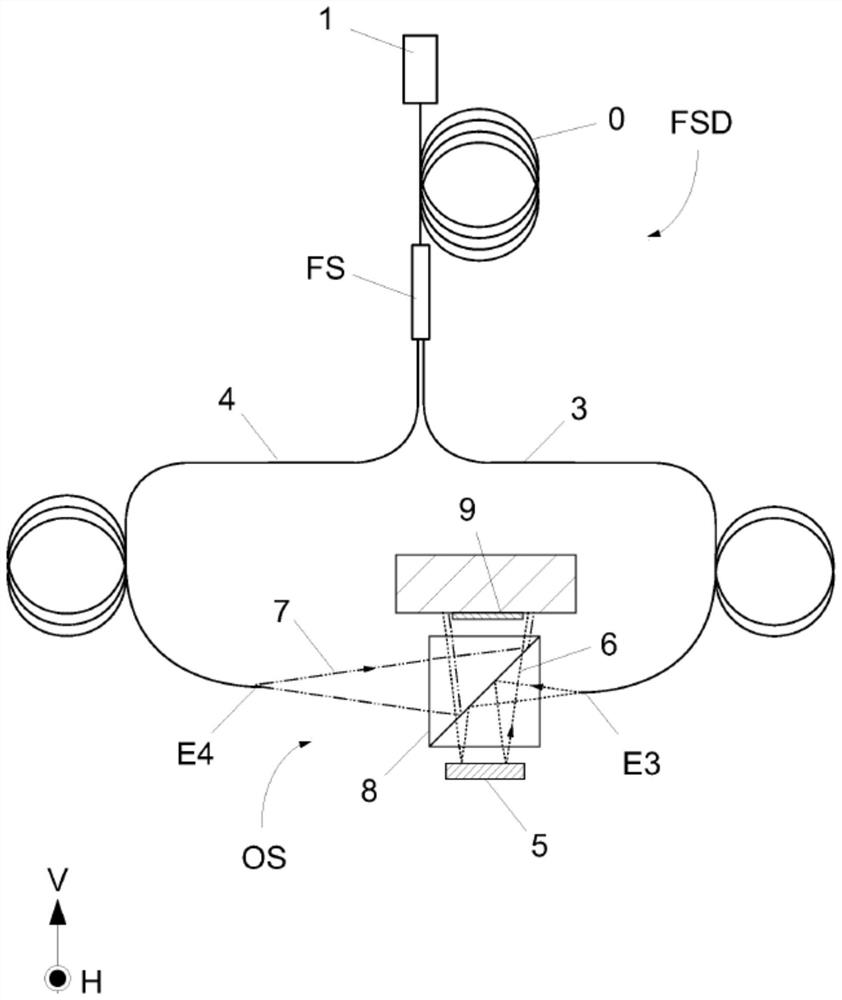
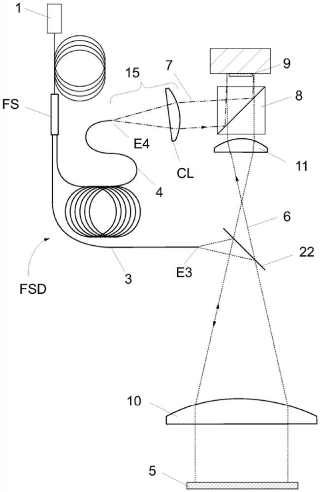
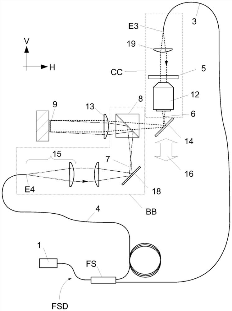
[0027] The fiber optic splitter device (FSD) of the present invention includes at least 3 fibers. The first 0 collects the light from the light source (1), the second is called the target fiber (3), and the third is called the reference fiber (4). The fiber splitter FS splits the light from the light source (1) into target and reference fibers, the target and reference fibers deliver the light to an optical device OS configured to generate by recombining the light delivered by the target and reference fibers put one's oar in.

[0028] Interference occurs between the reference wave (7) and the target wave (6). The target wave (6) is generated by the interaction of the light delivered by the target fiber (3) with the sample (5). The reference wave (7) is emitted by the light delivered by the reference fiber (4) without interacting with the sample. The interference between the target wave (6) and the reference wave (7) produces a hologram or interferogram recorded by the image...


PUM

PropertyMeasurementUnit
refractive indexaaaaaaaaaa

Abstract

An optical fiber splitter device is disclosed that includes at least two optical fibers of different lengths for partially or fully compensating for optical path differences between waves that interfere to produce a hologram or interferogram. Various embodiments of the fiber optic splitter device are described in Devices for Holographic and Interferometric Imaging of Microscopic and Larger Samples.

Description

[0001] field of invention [0002] The present invention relates to the field of holography and interference imaging. Background technique [0003] Holographic or interferometric imaging methods are used to characterize the phase and intensity (or amplitude) contrast of a sample. Phase information is quantitative and of particular interest as it enables surface topography measurements on reflective samples, and thickness or refractive index measurements using transparent samples. Furthermore, in cellular imaging, quantitative phase measurements (QPM) have been demonstrated to monitor changes in morphology, intracellular concentration, channel activity, and other cellular processes. Holographic and interferometric imaging methods are optimally implemented using image sensors that provide digital images of optically generated interference patterns or holograms, from which quantitative phase contrast images are generated by applying specific image processing methods. [0004] T...

Claims


Application Information

Patent Timeline
Patent Type & Authority Patents(China)
IPC IPC(8): G02B21/06G01J9/02G03H1/08G03H1/04G02B27/10G03H1/00
CPCG03H2001/0469G02B21/06G02B27/10G03H2001/005G03H1/0443G01B9/02091G01B9/02028G01B9/02007G01B2290/70G03H2001/0456G03H2223/16G03H2223/26G03H1/041G01B9/021G01N21/453G01N2021/4186G01N2021/458G01N2201/082G01N2201/0846G02B21/14G02B27/14G03H1/0005G03H1/0465G03H2001/0452G03H2001/0471G03H2223/24
Inventor E·库什伊夫·埃默里
Owner LYNCEE TEC
Features
  • R&D
  • Intellectual Property
  • Life Sciences
  • Materials
  • Tech Scout
  • Unparalleled Data Quality
  • Higher Quality Content
  • 60% Fewer Hallucinations
Learn More