Valve cleaning device

A technology for cleaning equipment and valves, applied to heart valves, cleaning methods and utensils, cleaning methods using liquids, etc., can solve the problems of uneven cleaning, incomplete cleaning, waste of resources, etc. clean effect

Pending Publication Date: 2019-05-28
韦秋英
View PDF0 Cites 6 Cited by
  • Summary
  • Abstract
  • Description
  • Claims
  • Application Information

AI Technical Summary

Problems solved by technology

[0005] The purpose of the present invention is to provide a valve cleaning device to solve the problems of incomplete cleaning and waste of resources caused by uneven cleaning of traditional manual washing proposed in the background art

Method used


Image

  • Valve cleaning device
  • Valve cleaning device
  • Valve cleaning device

Examples


Embodiment Construction

[0023] The following will clearly and completely describe the technical solutions in the embodiments of the present invention with reference to the accompanying drawings in the embodiments of the present invention. Obviously, the described embodiments are only some, not all, embodiments of the present invention. Based on the embodiments of the present invention, all other embodiments obtained by persons of ordinary skill in the art without making creative efforts belong to the protection scope of the present invention.

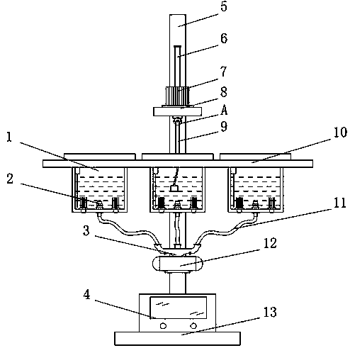
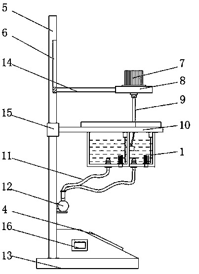
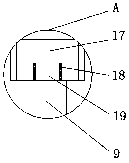
[0024] see Figure 1-5 , an embodiment provided by the present invention: a valve cleaning device, including a cleaning basin 1, a bottom plate 13 and a valve holder 9, one end of the top of the bottom plate 13 is vertically fixed with a support rod 5, and the other end of the top of the support rod 5 Console 4 is installed, and the interior of console 4 is provided with single-chip microcomputer 16, and the model of single-chip microcomputer 16 can be HT66F01...


PUM


Abstract

The invention discloses a valve cleaning device which comprises cleaning basins, a bottom plate and a valve holding device; a supporting rod is vertically fixed to one end of the top of the bottom plate; a control table is mounted at the other end of the top of the supporting rod; a single chip microcomputer is arranged inside the control table; a motor is mounted at the top end of a supporting plate; a locating block is fixed to the bottom end of the motor by means of a rotating shaft; a reserving groove is formed in the bottom end of the locating block; the valve holding device is fixed to the bottom end of the locating block; and an output end of the single chip microcomputer is electrically connected with input ends of an electric slide rail, the motor and an air pump through a wire. The motor is arranged, the locating block is fixed to the output end of the motor by means of the rotating shaft, the valve holding device is fixed to the bottom end of the locating block, the bottom end of the valve holding device is spirally connected with a bioprosthetic valve, and when the motor works, the valve holding device is conveniently driven to rotate, so that the bioprosthetic valve isfavorably cleaned, preserving fluid on the surface of the bioprosthetic valve is favorably cleared away, and the personnel cost is favorably reduced.

Description

technical field [0001] The invention relates to the technical field of medical aids, in particular to valve cleaning equipment. Background technique [0002] Artificial heart valve (Heart Valve Prothesis) is an artificial organ that can be implanted in the heart to replace the heart valve (aortic valve, tricuspid valve, mitral valve), which can make blood flow in one direction and has the function of a natural heart valve. When the heart valve When the lesions are too serious to recover or improve the valve function by valve separation or repair surgery, artificial heart valve replacement must be used. Artificial valves are divided into two categories according to the materials used: one is all made of artificial materials called artificial heart valves. Mechanical valve; the other is a biological valve made entirely or partly of biological tissue; [0003] The preservation of biological valves is sealed and soaked in the preservation solution containing fungicides. The pre...

Claims


Application Information

Patent Timeline
Patent Type & Authority Applications(China)
IPC IPC(8): A61F2/24B08B3/08B08B3/10
Inventor 韦秋英郑丽萍崔妙玲关心洪梅龙一杞刘晓余关妮许盈莹谢园园刘菊梅郑宝石
Owner 韦秋英
Why Eureka
Try Eureka