Wire electric arc additive manufacturing method of copper alloy

A technology of additive manufacturing and copper alloy, which is applied in the field of wire arc additive manufacturing of copper alloy, can solve the problems of limited action area of ​​stirring pin, coarsening of microstructure, and degradation of additive body performance, so as to improve mechanical properties , prevent microstructure coarsening, and high flexibility

Active Publication Date: 2019-05-28
NORTHEASTERN UNIV
View PDF8 Cites 5 Cited by
  • Summary
  • Abstract
  • Description
  • Claims
  • Application Information

AI Technical Summary

Problems solved by technology

However, when the additive body is modified by the method of friction stir processing, the action area of ​​the stirring pin is limited, and the metal on the side wall of the additive body is difficult to be processed, and the metal on the side wall still retains the characteristics of the casting structure; in a

Method used


Image

  • Wire electric arc additive manufacturing method of copper alloy
  • Wire electric arc additive manufacturing method of copper alloy
  • Wire electric arc additive manufacturing method of copper alloy

Examples


Embodiment 1

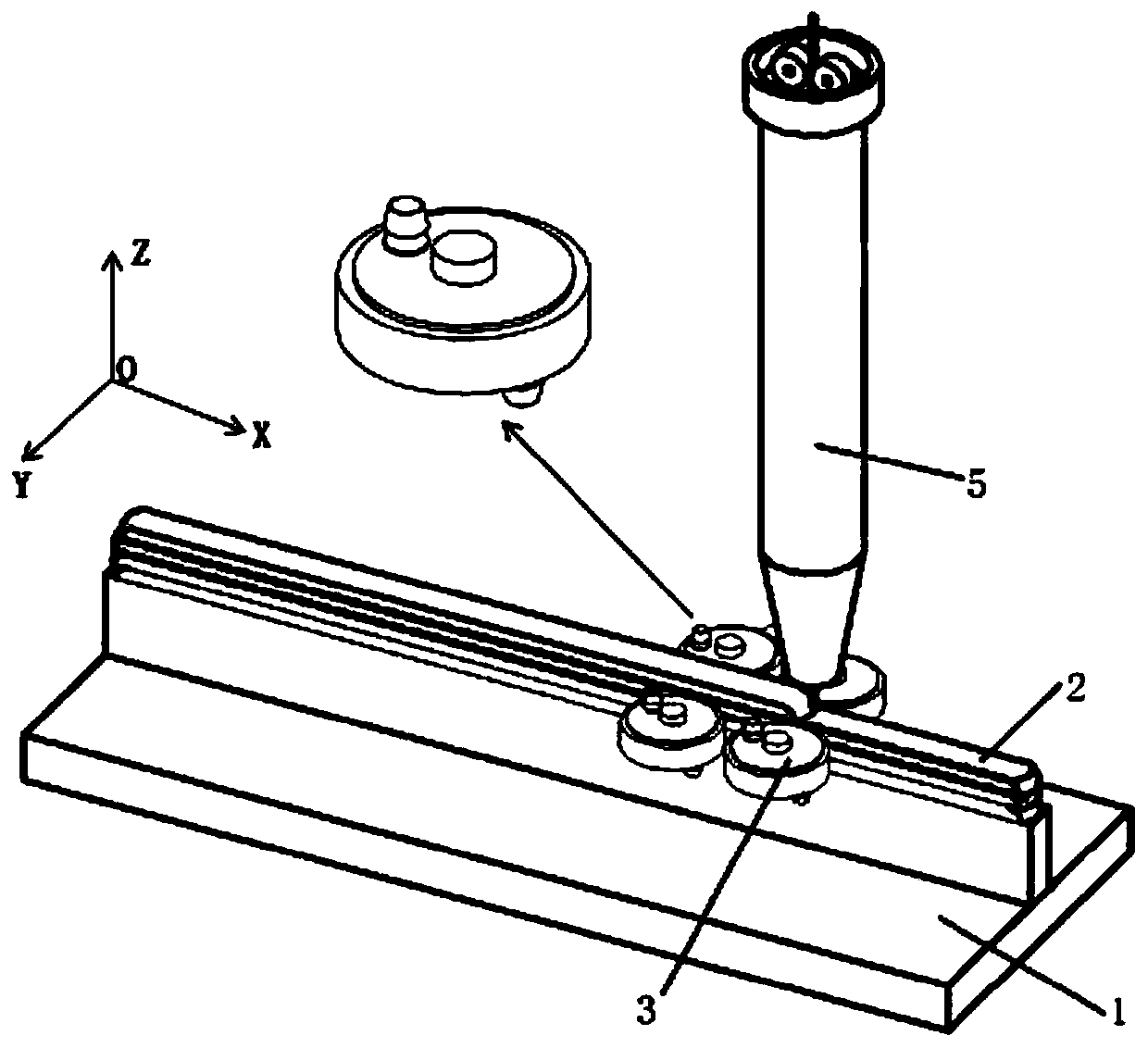
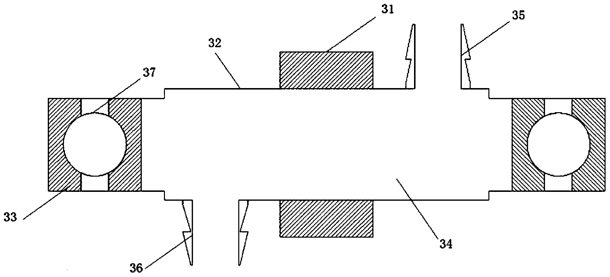
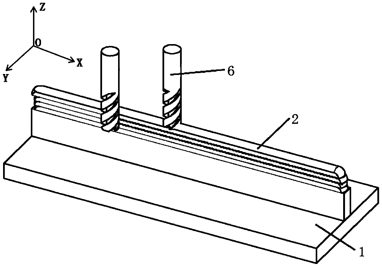
[0032] Such as Figure 1 ~ Figure 4 As shown, this example provides CuAl8 wire arc additive manufacturing method for straight wall, comprising the following steps:

[0033] Step 1. Use cooling roller to assist arc additive forming: Use 3D drawing software to draw a straight wall model with a size of 200mm (length) × 50mm (height) × 16mm (width), and use slicing software to layer the part model Slice processing, obtain layered slice data, use simulation software to simulate layered slice data and optimize the forming path, generate robot control code (or NC code), import robot control code into welding robot, use welding robot, adopt The arc generated by the TIG welding machine is used as the heat source, and CuAl8 copper alloy wire arc additive forming is performed on the T-shaped substrate 1 prepared in advance, and a total of 2 to 4 layers are deposited to form a multi-layer deposited metal 2. The formed multi-layer deposited metal The width of 2 is 16mm, and the multilay...

Embodiment 2

[0044] This example provides CuAl8 wire arc additive manufacturing method for straight wall, comprising the following steps:

[0045] Step 1. Use cooling roller to assist arc additive forming: Use 3D drawing software to draw a straight wall model with a size of 200mm (length) × 50mm (height) × 40mm (width), and use slicing software to layer the part model Slice processing, obtain layered slice data, use simulation software to simulate layered slice data and optimize the forming path, generate robot control code (or NC code), import robot control code into welding robot, use welding robot, adopt The arc generated by the TIG welding machine is used as the heat source, and CuAl8 copper alloy wire arc additive forming is performed on the T-shaped substrate 1 prepared in advance, and a total of 2 to 4 layers are deposited to form a multi-layer deposited metal 2. The formed multi-layer deposited metal The width of 2 is 40mm, and the multi-layer deposited metal 2 is obtained by mul...


PUM

PropertyMeasurementUnit
Widthaaaaaaaaaa

Abstract

A wire electric arc additive manufacturing method of a copper alloy comprises the following steps: 1, forming an electric arc additive with the supporting of cooling rolling; 2, milling the side surface and the top surface of an additive body; 3, stirring and rubbing the additive body through the stirring rubbing processing device; and cooling and rolling the sidewall of the additive body througha cooling rolling device during stirring rubbing processing; 4, finely milling the upper surface of the additive body in order to prepare for the next electric arc additive formation; and 5, circularly repeatedly performing the abovementioned steps until a part is finally formed. With the adoption of the method, dendritic growth in the copper alloy additive forming process can be completely avoided, and crystal grains can be refined, and defects such as air pores and cracks can be effectively recovered; and meanwhile, cooling is carried out during wire electric arc additive manufacturing and modifying, so that the additive body is prevented from overheat which leads to alligatoring of a microstructure, and as a result, the mechanical performance, particularly the plasticity and the fatigueperformance, of the additive body can be greatly improved.

Description

technical field [0001] The invention belongs to the technical field of metal additive manufacturing, and relates to a wire arc additive manufacturing method for copper alloys, in particular to a wire arc additive manufacturing method for copper alloys aided by cooling roll pressing and friction stir processing. Background technique [0002] Metal wire arc additive manufacturing (Wire and Arc Additive Manufacture, WAAM) uses gas metal arc welding (GMAW), argon tungsten arc welding (GTAW) or plasma arc welding (PAW) as the heat source, using discrete, The principle of stacking is an advanced manufacturing technology for surfacing and welding three-dimensional metal parts layer by layer from line-surface-body under the control of the program through the addition of metal wires according to the three-dimensional digital model. Compared with the additive manufacturing technology using laser and electron beam as heat source, it has the following advantages: 1) high deposition rate...

Claims


Application Information

Patent Timeline
IPC IPC(8): B23P15/00
Inventor 何长树韦景勋李颖田妮秦高梧
Owner NORTHEASTERN UNIV
Why Eureka
Try Eureka