A Fan Formed Processing Method of Microlens Array Optical Components

A microlens array and optical element technology, applied in the direction of optical surface grinders, metal processing equipment, manufacturing tools, etc., can solve the problems of tool wear, material limited surface accuracy, etc., to improve surface accuracy and ensure surface accuracy And dimensional consistency, the effect of strong wear resistance

Active Publication Date: 2021-09-17
HARBIN INST OF TECH
View PDF7 Cites 0 Cited by
  • Summary
  • Abstract
  • Description
  • Claims
  • Application Information

AI Technical Summary

Problems solved by technology

[0005] The present invention aims to solve the problems of tool wear, limited material and poor surface accuracy existing in the existing microlens array method

Method used


Image

  • A Fan Formed Processing Method of Microlens Array Optical Components
  • A Fan Formed Processing Method of Microlens Array Optical Components
  • A Fan Formed Processing Method of Microlens Array Optical Components

Examples


specific Embodiment approach 1

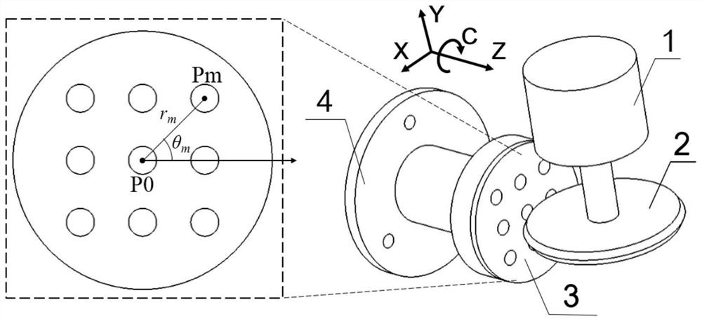
[0035] Specific implementation mode one: combine Figure 1 to Figure 5 Describe this embodiment mode, a kind of microlens array optical element of this embodiment mode forms the formula processing method, comprises the following steps:

[0036] Step 1: According to the spherical diameter R of the lens unit on the microlens array optical element to be processed s , choose a radius larger than the spherical diameter R s V-shaped grinding wheel, install the V-shaped grinding wheel 2 on the grinding shaft 1 of the machine tool, and then perform in-situ precision dressing on the V-shaped grinding wheel 2 to achieve a sharp grinding wheel tip and an accurate grinding wheel radius R g ;

[0037]Step 2: Through the tool setting operation, make the sharp point of the V-shaped grinding wheel 2 along the negative direction of the Z axis of the machine tool coincide with the center line of the C axis of the machine tool;

[0038] Step 3: Fix the workpiece 3 to be processed on the front...

specific Embodiment approach 2

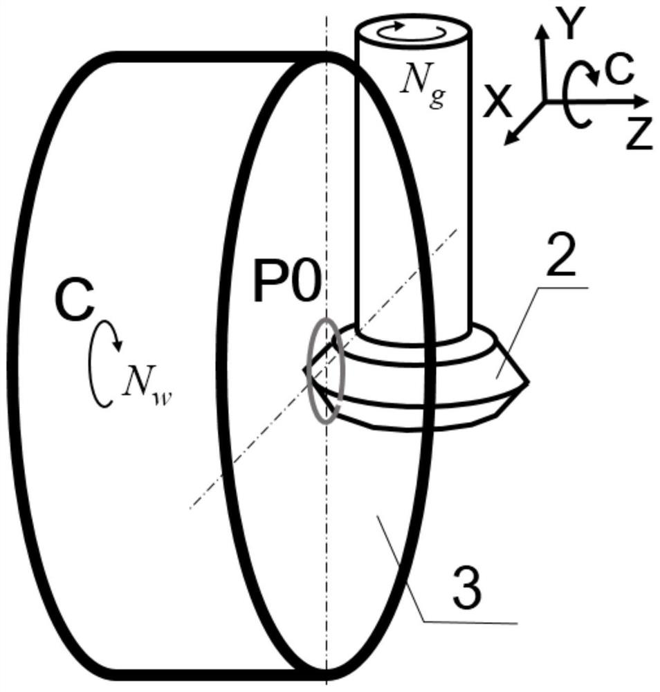
[0042] Specific implementation mode two: combination Figure 1 to Figure 5 Illustrate this embodiment, the specific process of processing any microlens Pm of non-workpiece center position in the step 5 of this embodiment is:

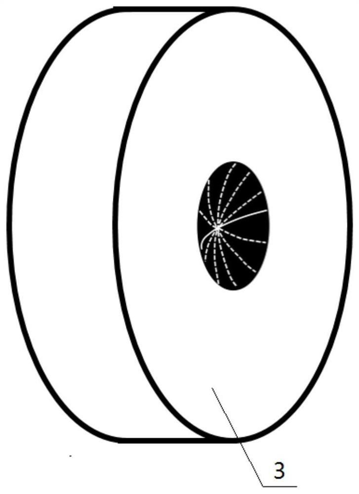
[0043] First rotate the C axis of the machine tool clockwise by an angle θ m , and then let the X-axis of the machine tool move along the positive direction for a distance r m , so that the sharp point of the V-shaped grinding wheel 2 along the negative direction of the Z-axis of the machine tool coincides with the center line of the microlens to be processed, and the speed of the V-shaped grinding wheel 2 is set to N g , the feed rate is V f , so that the V-shaped grinding wheel 2 is fed in the negative direction along the Z axis of the machine tool until a depth of a is produced on the workpiece 3 p Then, the Z axis of the machine tool stops feeding and keeps the position still. Then, the X axis, Y axis and C axis of the machine tool perform three-a...

specific Embodiment approach 3

[0045] Specific implementation mode three: combination Figure 1 to Figure 5 Describe this embodiment, in step 1 of this embodiment, each unit lens in the microlens array is a concave spherical lens, the diameter range of the unit lens is 0.1 mm to 10 mm, and the spherical diameter R of the unit lens is s The range is 5mm ~ 100mm. Such setting is because the processing method proposed by the present invention still has certain limitations. The diameter of the unit lens and the spherical diameter of the microlens array optical element are not within the given range. The diameter of the grinding wheel required for processing is too small or too large. Cannot be installed on the lathe, thereby is not suitable for adopting the processing method that the present invention proposes. Giving these parameter limits here in advance can provide design constraints for the optical design stage of the microlens array optical element, and prevent the designed optical element drawings from b...


PUM


Abstract

The invention relates to a fan-form processing method of a microlens array optical element, relating to a fan-form processing method. The invention solves the problems of tool wear, limited material and poor surface precision in the existing microlens array processing method. The present invention selects the V-shaped grinding wheel whose radius is greater than the microlens ball diameter Rs and trims it; the sharp point of the V-shaped grinding wheel along the negative Z axis of the machine tool just coincides with the center line of the C axis of the machine tool; Microlens P0, set the speed of the V-shaped grinding wheel to N g , the feed rate is V f , so that the V-shaped grinding wheel is fed in the negative direction along the Z-axis of the machine tool until a depth of a is produced on the workpiece. p wear marks, then the Z-axis of the machine tool stops feeding and remains still, and the C-axis of the machine tool rotates at N w Rotate 360° clockwise, retract the tool in the positive direction of the Z axis; use the Fancheng method to process any microlens P that is not at the center of the workpiece m ; Processing in sequence to form a microlens array optical element. The invention is used for the processing of microlens array optical elements.

Description

technical field [0001] The invention relates to a fan-form processing method, in particular to a fan-form processing method of a microlens array optical element, and belongs to the technical field of precision processing of microstructure optical elements. Background technique [0002] The microlens array optical element is a bionic structure designed by humans to realize some functions of insect compound eyes. Insect compound eyes have the characteristics of small size, large field of view, and high resolution of objects at close range. They are of great importance in medical equipment and military affairs. application potential. For the processing of the micro-spherical concave lens array, the surface accuracy of the micro-lens unit, the surface roughness of the micro-lens unit and the size consistency of each micro-lens unit should be considered. [0003] At present, there are many processing methods for microlens array optical components, such as photolithography hot me...

Claims


Application Information

Patent Timeline
Patent Type & Authority Patents(China)
IPC IPC(8): B24B13/005B24B13/00B24B47/20B24B47/22B24B55/00B24B13/01
Inventor 赵清亮潘永成郭兵白云峰
Owner HARBIN INST OF TECH
Why Eureka
Try Eureka