
A heat exchanger for waste heat utilization of flue gas

A flue gas waste heat and heat exchanger technology, which is applied in the direction of indirect heat exchangers, heat exchanger types, heat exchanger shells, etc., can solve the disadvantages of strengthening flue gas heat transfer, increasing the cost of boiler system equipment, and not compact structure, etc. problems, to achieve the effect of compact structure, high heat utilization efficiency, and prolonged contact time

Active Publication Date: 2020-04-28
HUAZHONG UNIV OF SCI & TECH
View PDF8 Cites 0 Cited by
  • Summary
  • Abstract
  • Description
  • Claims
  • Application Information

AI Technical Summary

Problems solved by technology

The economizer and air heat exchanger in the traditional boiler system increase the equipment cost of the boiler system, and when used in a pressurized system, due to the reduced volume of flue gas, its structure is not compact, which is not conducive to enhancing the heat transfer of flue gas

Method used


Image

  • A heat exchanger for waste heat utilization of flue gas
  • A heat exchanger for waste heat utilization of flue gas

Examples


Embodiment 1

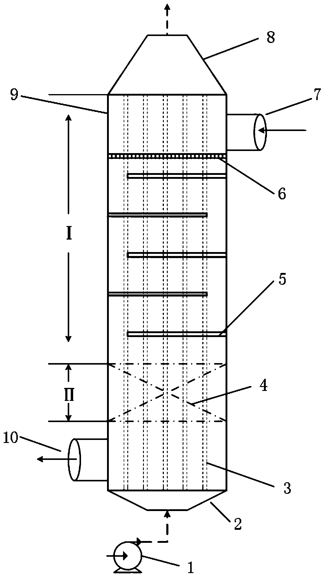
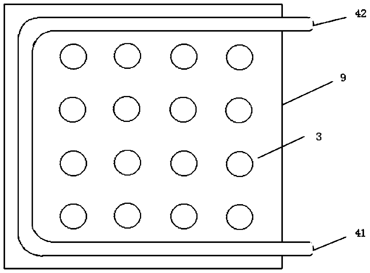
[0030] Such as figure 1 As shown, this embodiment provides a heat exchanger for waste heat utilization of flue gas, including a first flue 9, a second flue 4, a heat exchange tube 3, a baffle plate 5 and a filter plate 6;

[0031] Specifically, the first flue is set as follows: the first flue 9 is placed vertically, the first flue inlet 7 is arranged at the upper part of one side, and the first flue outlet 10 is arranged at the lower part of the other side; the first flue 9 can It is a regular long column shape such as a cuboid or cylinder.

[0032] Both the baffle plate 5 and the filter plate 6 are fixedly connected in the first flue 9, and the baffle plate 5 is downstream of the filter plate 6; the second flue 4 penetrates the first flue 9, the second flue 4 is arranged downstream of the baffle 5; the heat exchange tube 3 penetrates the first flue 9, the baffle 5 and the filter plate 6, and the flue gas enters the first flue 9 , first pass through the filter plate 6 to fil...

Embodiment 2

[0042] Such as figure 1 As shown, this embodiment provides a heat exchanger for utilization of flue gas waste heat.

[0043] On the basis of Embodiment 1, the connection method of the baffle plate 5 and the filter plate 6 is improved.

[0044] Specifically, another setting method of the baffle 5 is: the baffle 5 is detachably installed on the inner wall of the first flue.

[0045]Specifically, another arrangement of the filter plate 6 is: the filter plate 6 is detachably arranged near the entrance of the first flue. Filter the solid particles with large particle size in the flue gas.


PUM


Abstract

The invention relates to a heat exchanger for flue gas waste heat utilization and belongs to the technical field of heat exchange devices. The heat exchanger comprises a first flue, a second flue, heat exchange pipes, baffle plates and a filtering plate; the baffle plates and the filtering plate are all arranged in the first flue; the baffle plates are arranged downstream of the filtering plate; the second flue penetrates through the first flue and is arranged downstream of the baffle plates; and the heat exchange pipes penetrate through the first flue, the baffle plates and the filtering plate. For the heat exchanger, by adopting classification heat exchange, water / steam-raw gas heat exchange and raw gas-circulating flue gas heat exchange are performed at the same time, and the heat exchange effect is equivalent to the effect of the traditional coal economizer and air preheater; the whole heat exchange process fully utilizes waste heat in flue gas produced by a pressurized oxygen-enriched combustion boiler, and the heat exchanger has the advantages of compact structure, high heat utilization efficiency and the like.

Description

technical field [0001] The invention relates to a heat exchanger for utilizing waste heat of flue gas, and belongs to the technical field of heat exchange devices. Background technique [0002] Oxygen-enriched combustion technology can capture CO produced by fossil fuel combustion on a large scale 2 , great potential for development. It is characterized in that it uses fuel combustion flue gas mixed with pure oxygen (the total oxygen content is 25-35vol%) instead of air as a combustion aid. Compared with traditional air combustion, due to the separation of nitrogen before combustion and the continuous flue gas circulation during combustion, the CO in dry flue gas 2 The concentration can reach more than 80%, which is beneficial to CO 2 storage and utilization. However, the current oxygen-enriched combustion technology is carried out under normal pressure, and the energy consumption generated by the air separation device, flue gas circulation and flue gas purification all ...

Claims


Application Information

Patent Timeline
Patent Type & Authority Patents(China)
IPC IPC(8): F28D1/053F28F9/22F23J15/02
CPCY02E20/34
Inventor 张立麒张泽武李小姗罗聪鲁博文赵征鸿陈爱玲李诗谙
Owner HUAZHONG UNIV OF SCI & TECH
Learn More