
Coherent signal transceiving method and device and coherent passive optical network system

A passive optical network and coherent signal technology, applied in the field of passive optical network, can solve the problems of increased cost, high complexity of ICR, unsuitable for wide use, etc., and achieve the effect of simplifying design complexity and reducing device cost

Active Publication Date: 2019-05-28
FENGHUO COMM SCI & TECH CO LTD
View PDF5 Cites 10 Cited by
  • Summary
  • Abstract
  • Description
  • Claims
  • Application Information

AI Technical Summary

Problems solved by technology

[0005] 1) A narrow linewidth light source must be used, the fluctuation range of the light source wavelength is within + / -0.01nm, the control accuracy is high, and the cost is increased
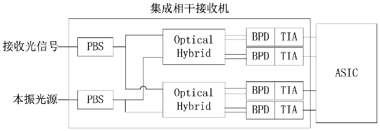
[0006] 2) The complexity of ICR is high, such as image 3 As shown, it includes two PBS (Polarization BeamSplitter, polarization beam splitter), two 90-degree Optical Hybrid (optical mixer) with 4 output optical ports, four BPD (Balanced Photo Detector, balance detector), and Four TIA (Trans-Impedance Amplifier, transimpedance amplifier)
[0008] In summary, the existing coherent light detection schemes have a high overall cost and are not suitable for widespread use

Method used


Image

  • Coherent signal transceiving method and device and coherent passive optical network system
  • Coherent signal transceiving method and device and coherent passive optical network system
  • Coherent signal transceiving method and device and coherent passive optical network system

Examples


Embodiment Construction

[0074] The present invention will be described in further detail below in conjunction with the accompanying drawings and embodiments.

[0075] The present invention provides an embodiment of a coherent signal transmission method, including the steps of: generating a continuous optical signal through a wide-linewidth light source device, and dividing it into two optical signals with the same light intensity, and each optical signal is used as an optical signal of an optical modulator Carrier, and the optical intensity modulator is driven by an electric drive signal to perform optical signal modulation, and the two modulated optical signals are combined to generate a polarization-multiplexed intensity-modulated optical signal and sent out. Wherein, the wide-linewidth light source device may be a wide-linewidth laser, such as a DFB (Distributed Feedback Laser, distributed feedback laser).

[0076] Preferably, the generated linewidth is greater than 10MHz, and the fluctuation rang...


PUM


Abstract

The invention discloses a coherent signal transceiving method and device and a coherent passive optical network system, and relates to the field of passive optical networks. The system comprises a coherent signal transmitting device and a coherent signal receiving device, wherein the coherent signal sending device divides an optical signal of the wide-linewidth light source device into two paths with the same light intensity, each path is used as an optical carrier of a light intensity modulator, the light intensity modulator is driven by an electric driving signal to carry out optical signalmodulation, and the two paths of modulated optical signals are sent to an optical distribution network after being subjected to polarization beam combination; The coherent signal receiving device divides the local oscillation light and the received light signal into X polarized light and Y polarized light which are perpendicular to each other, and the light field intensities of the X polarized light and the Y polarized light divided by the local oscillation light are equal; Two beams of X-polarized light are mixed, two beams of Y-polarized light are mixed, light signals output after mixing aredetected by a single-ended photoelectric detector, and signal recovery is carried out through envelope detection after trans-impedance amplification and blocking. The total cost of coherent light detection can be reduced.

Description

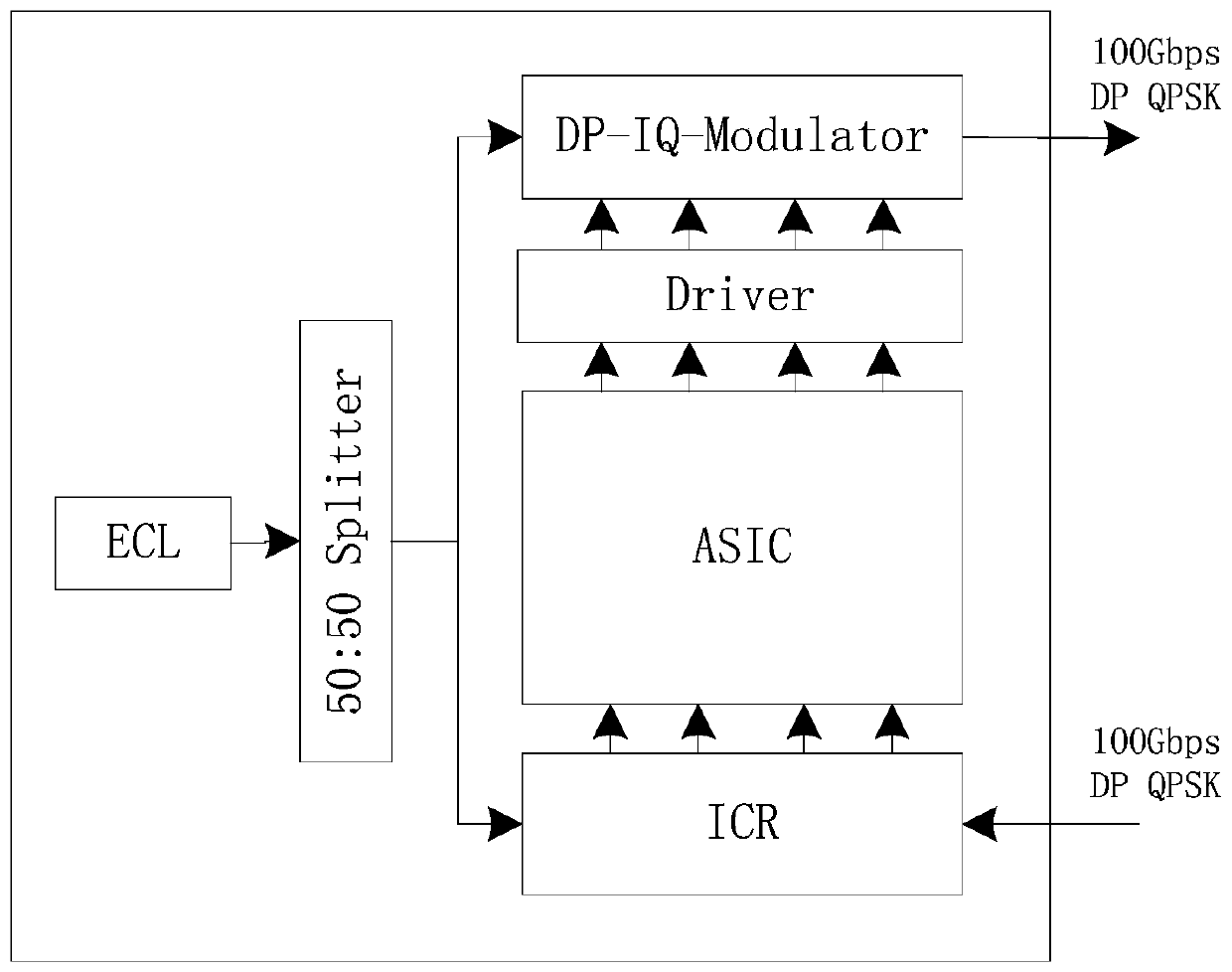
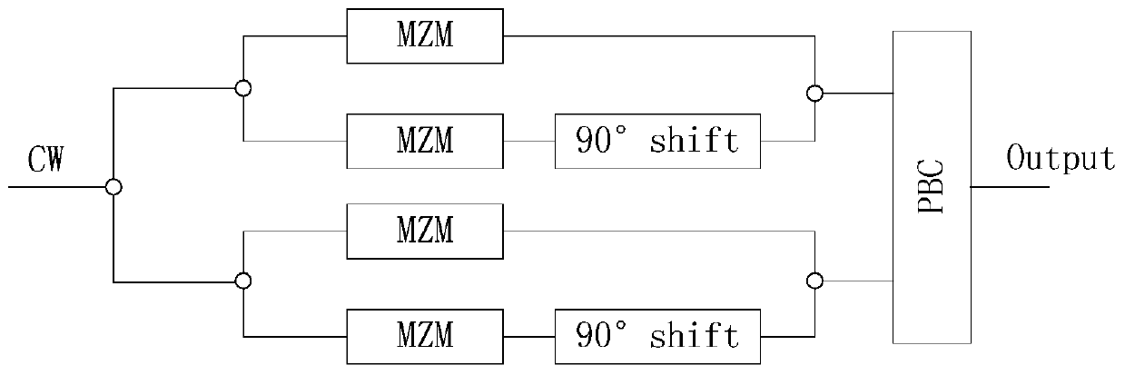
technical field [0001] The invention relates to the field of passive optical networks, in particular to a coherent signal sending and receiving method and device and a coherent passive optical network system. Background technique [0002] In the field of long-distance optical transmission, coherent optical detection has gradually replaced direct detection and has become the mainstream optical transport network technology. figure 1 Shows a schematic block diagram of a 100Gb / sDP-QPSK (Dual-Polarization Quadrature Phase-Shit Keying, dual-polarization quadrature phase-shift keying) modulated coherent optical transceiver system, including: wavelength-tunable narrow linewidth ECL (External Cavity Laser, External cavity laser), 50:50Splitter (50:50 splitter), Driver (signal driver), DP-IQ-Modulator (Dual-PolarizationIQ-Modulator, dual polarization IQ modulator), ICR (Integrated Coherent Receiver, integrated coherent reception Machine), and digital transceiver ASIC (Application Spe...

Claims


Application Information

Patent Timeline
IPC IPC(8): H04B10/54H04B10/61
CPCH04B10/54H04B10/61
Inventor 胡荣
Owner FENGHUO COMM SCI & TECH CO LTD
Learn More