
Rotary positioning device based on accumulating chain

A positioning device and the technology of product chain, which is applied in the field of product chain, can solve the problems of inability to rotate and position materials, increase equipment investment costs, multiple workshop areas and spaces, etc., to ensure accurate spraying, improve equipment operation efficiency, and facilitate later stages The effect of maintenance

Pending Publication Date: 2019-05-31
天津七所高科技有限公司
View PDF0 Cites 1 Cited by
  • Summary
  • Abstract
  • Description
  • Claims
  • Application Information

AI Technical Summary

Problems solved by technology

However, only through the cooperation of the stopper and the front and rear trolleys to realize the accumulation of the workpiece, it is often impossible to ensure that the workpiece stops at an accurate position, and the accumulation trolley cannot drive the material to rotate and position
Especially in the key process of painting and powder spraying, the traditional method is to set up spraying stations before and after the product chain, distribute on both sides of the product chain, and spray in steps, which not only increases the equipment investment cost, but also occupies more equipment. Plant area and space, for this reason, we propose a rotary positioning device based on accumulation chains to solve the above problems

Method used


Image

  • Rotary positioning device based on accumulating chain
  • Rotary positioning device based on accumulating chain
  • Rotary positioning device based on accumulating chain

Examples


Embodiment 1

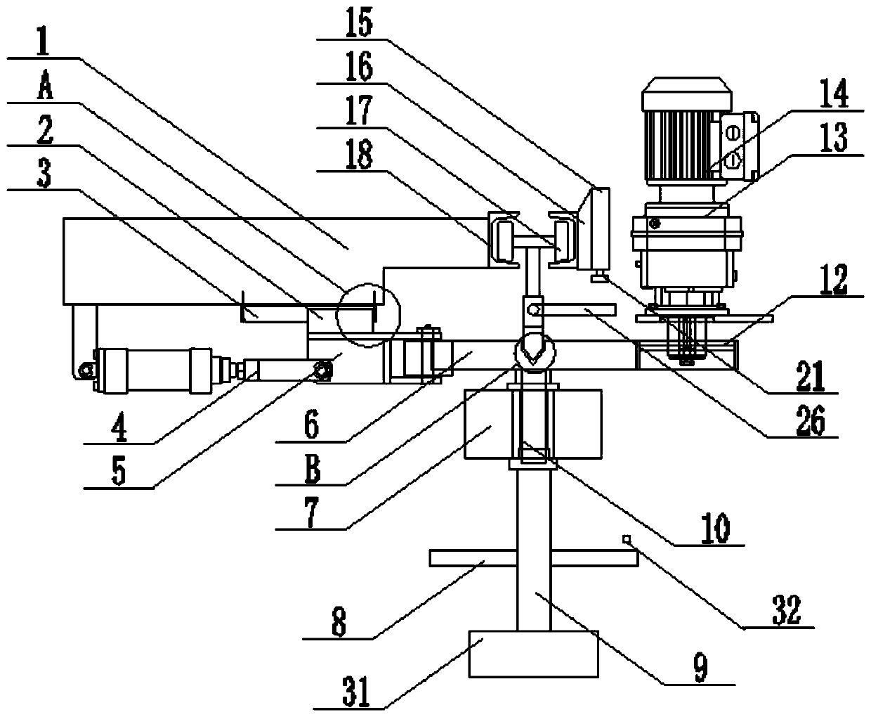
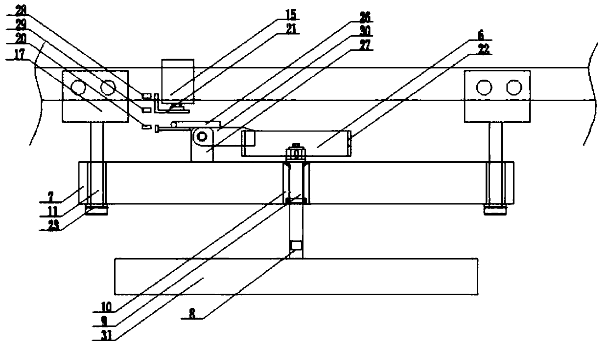
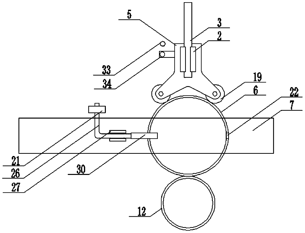
[0030] refer to figure 1 , 2 , 3, 5, a kind of rotary positioning device based on accumulation chain, comprise two rails 18, two moving mechanisms 17 are installed jointly between two rails 18, facilitate moving mechanism 17 to move stably, the two moving mechanisms 17 The lower ends are fixed with bearing rods 11. When the moving mechanism 17 moves, it drives the bearing rods 11 to move. The lower ends of the two bearing rods 11 run through the bearing blocks 7. The movement of the bearing rods 11 drives the bearing blocks 7 to move. Bearing 10 is installed, and one side of the upper end of bearing block 7 is fixed with support rod 27, and the upper end of support rod 27 is connected with lifting pin fork 30 in rotation, and the upper end of lifting pin fork 30 is fixed with fixed plate 26, and fixed plate 26 moves to drive The pin lifting swing bar 30 moves, and under the action of the moving mechanism 17, the position of the friction wheel 6 is conveniently adjusted;

[0...

Embodiment 2

[0036] refer to figure 1 , 2, 3, 5, a kind of rotary positioning device based on accumulation chain, comprise two rails 18, two moving mechanisms 17 are installed jointly between two rails 18, facilitate moving mechanism 17 to move stably, the two moving mechanisms 17 The lower ends are fixed with bearing rods 11. When the moving mechanism 17 moves, it drives the bearing rods 11 to move. The lower ends of the two bearing rods 11 run through the bearing blocks 7. The movement of the bearing rods 11 drives the bearing blocks 7 to move. Bearing 10 is installed, and one side of the upper end of bearing block 7 is fixed with support rod 27, and the upper end of support rod 27 is connected with lifting pin fork 30 in rotation, and the upper end of lifting pin fork 30 is fixed with fixed plate 26, and fixed plate 26 moves to drive The pin lifting swing bar 30 moves, and under the action of the moving mechanism 17, the position of the friction wheel 6 is conveniently adjusted;

[00...

Embodiment 3

[0043] refer to figure 1 , 2 , 3, 4, 5, a kind of rotary positioning device based on accumulation chains, including two rails 18, two moving mechanisms 17 are installed between the two rails 18, to facilitate the stable movement of the moving mechanism 17, the two moving mechanisms The lower ends of 17 are fixed with bearing rods 11, and when the moving mechanism 17 moves, it drives the bearing rods 11 to move. The lower ends of the two bearing rods 11 run through the bearing blocks 7, and the moving of the bearing rods 11 drives the bearing blocks 7 to move. A bearing 10 is installed in the middle part of the upper end, and a support rod 27 is fixed on one side of the upper end of the bearing block 7, and the upper end of the support rod 27 is rotatably connected with a lifting pin swing rod 30, and the upper end of the lifting pin swing rod 30 is fixed with a fixed plate 26, and the fixed plate 26 The movement drives the pin lifting swing bar 30 to move, and under the actio...


PUM


Abstract

The invention discloses a rotary positioning device based on an accumulating chain. The rotary positioning device comprises two rails, wherein two movable mechanisms are co-mounted between the two rails; the lower ends of the two movable mechanism are fixedly equipped with bearing rods; the lower ends of the two bearing rods are equipped with a bearing block in a penetrating mode; the middle partof the upper end of the bearing block is equipped with a bearing; one side of the upper end of the bearing block is fixedly equipped with a supporting rod; the upper end of the supporting rod is rotatably connected with a lifting pin swing rod; the upper end of the lifting pin swing rod is fixedly equipped with a fixed plate; one side of one rail is fixedly equipped with a connecting plate; one side of the connecting plate is fixedly equipped with a second gas cylinder; and the tail end of the piston rod of the second gas cylinder is fixedly equipped with an L-shaped plate. The rotary positioning device can be applied to a coating production line, and further can be applied to other related automatic production lines, so that labor intensity of a worker is reduced, and working efficiency is improved; and moreover, investment cost is reduced, a space occupation rate is reduced, and the application prospect is wide.

Description

technical field [0001] The invention relates to the technical field of accumulation chains, in particular to a rotary positioning device based on accumulation chains. Background technique [0002] The so-called coating refers to covering the metal and non-metal surfaces with protective or decorative layers. With the development of industrial technology, coating has developed from manual to industrial automation, and the degree of automation is getting higher and higher, so the application of coating production lines is becoming more and more extensive, and has penetrated into many fields of the national economy. [0003] In the modern high-speed development of automated coating lines, the product-free suspension conveyor (abbreviated as product-free chain) plays an irreplaceable role. It can not only undertake simple material handling functions, but also solve complex material storage and transportation problems. However, only through the cooperation of the stopper and the ...

Claims


Application Information

Patent Timeline
Patent Type & Authority Applications(China)
IPC IPC(8): B05B13/02
Inventor 许永攀元鑫唐耘杨凡秦忠玉
Owner 天津七所高科技有限公司
Learn More