Eureka AIR delivers breakthrough ideas for toughest innovation challenges, trusted by R&D personnel around the world.

Destressing process for ultrahigh-vacuum stainless steel cavity components

An ultra-high vacuum and stainless steel technology, applied in the field of stress relief technology, can solve problems such as increasing operating costs of enterprises, achieve the effects of preventing deformation and cracking, reducing peak stress, and improving efficiency

Active Publication Date: 2019-05-31
JIANGYIN GUANGKE PHOTOELECTRIC PRECISION EQUIP CO LTD
View PDF3 Cites 0 Cited by
  • Summary
  • Abstract
  • Description
  • Claims
  • Application Information

AI Technical Summary

Problems solved by technology

) There is no better way (at present, the test of the section line is realized by purchasing high-cost multi-functional exciters, which will undoubtedly increase the operating costs of many small and medium-sized enterprises)

Method used


Image

  • Destressing process for ultrahigh-vacuum stainless steel cavity components
  • Destressing process for ultrahigh-vacuum stainless steel cavity components
  • Destressing process for ultrahigh-vacuum stainless steel cavity components

Examples


Embodiment 1

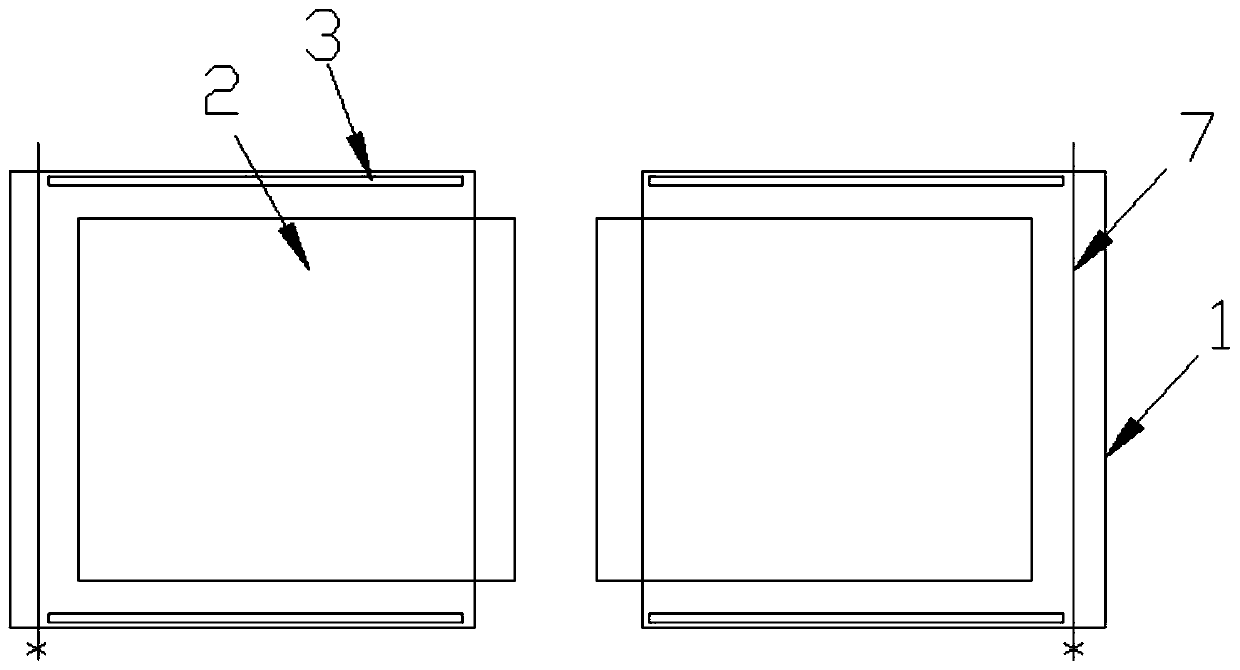
[0035] The present invention is a stress relief process for ultra-high vacuum stainless steel chamber components, such as Figure 1 to Figure 8 As shown, including the following process steps:

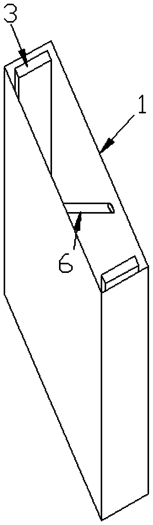
[0036] S1: When the stainless steel vacuum chamber plate 2 is welded, a flexible heat-insulating insulating sleeve 1 is set on the two plates, and the distance between the two flexible heat-insulating insulating sleeves 1 near the end of the weld is greater than that of the two plates after welding the width of the weld;

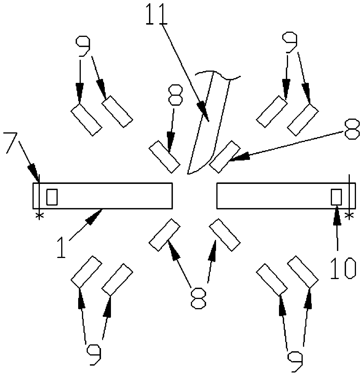
[0037] S2: After the flexible heat-insulating insulating sleeve 1 is set on the plate 2, the protruding rod 12 is fixedly connected to the lower part of the welding torch 11. Knock the bottom surface of the piece but the bottom end of the protruding rod 12 is provided with a distance from the surface of the plate 2; The top-facing blower 9 at the high altitude at the place and open the exhaust fan 10 at the end of the two flexible heat-insulating insulation sleeves...

Embodiment 2

[0041] The difference from Embodiment 1 is that, as Figure 9 , Figure 10 As shown, in the S3 step, the stress-relief tooling includes a rubber pad 16, a profiled cover 17 and a camera 18 matched with the profiled cover 17, the profiled cover 17 is oil clay, and the welded After the workpiece is placed on the rubber pad 16, cover the surface of the workpiece with oil clay and use the camera 18 to take pictures, turn on the vibrator 13 and start it for 5-10 minutes, then turn off the vibrator 13, then use the camera 18 to take pictures again, and compare the two images Find the peak and nodal line when the workpiece resonates, determine the best placement position and placement angle according to the peak and nodal line when the workpiece resonates, and start the vibrator 13 again after adjusting the workpiece to perform vibration stress relief.


PUM


Abstract

The invention discloses a destressing process for ultrahigh-vacuum stainless steel cavity components. The destressing process comprises the following process steps: when stainless steel vacuum cavityplates are welded, flexible thermal insulation sleeves sleeve two plates, and the distance of the end parts, near a welding line, of the two flexible thermal insulation sleeves is larger than the width of the welding line after welding of the two plates; after the flexible thermal insulation sleeves sleeve the plates, a convex rod is fixedly connected to the lower part of a welding gun; the lengthof the convex rod meets the conditions that the convex rod exceeds the bottom surfaces of welding knocking pieces arranged on the flexible thermal insulation sleeves and gaps are formed between the bottom end of the convex rod and the surfaces of the plates; then, an air blower and an exhaust fan are started; the welding is performed after the air blower and the exhaust fan are started; welded workpieces are placed on a vibration destressing tool; then, a vibration exciter is clamped on the workpieces by using two arch clampers, and the clamping position is arranged in one wave peak place inresonance of the workpieces; and a sensor is tightly absorbed in another wave peak place in resonance of the workpieces. The destressing process reduces the stress generation during welding.

Description

technical field [0001] The invention relates to a stress relief process for an ultra-high vacuum stainless steel chamber component. Background technique [0002] In the conventional welding process, the welding groove and the edge will generate a very high temperature, which is due to the local high temperature leading to a structural reorganization of the local metal. Taking 45# steel as an example, when it is processed, the steel is composed of atomic forms such as austenite and pearlite, and the toughness and hardness are moderate; and after a local high temperature (above 800 degrees), the local atomic results will be corresponding. There are cementite, austenite, martensite, etc., because the three have the properties of both, and the hardness is higher. Therefore, a new material band is produced between the material that has not passed through the high temperature and the material that has entered the high temperature. Due to the difference in atomic arrangement, the ...

Claims


Application Information

Patent Timeline
Patent Type & Authority Applications(China)
IPC IPC(8): C21D10/00C25F3/24
Inventor 瞿建强黄仕强
Owner JIANGYIN GUANGKE PHOTOELECTRIC PRECISION EQUIP CO LTD
Why Eureka
Eureka Blog
Learn More