
Power battery pack multi-stage heat dissipation system and control method based on coupling of planar heat pipe, liquid cooling and phase change energy storage heat conduction plate

A power battery pack, phase change energy storage technology, applied in battery/fuel cell control devices, vehicle energy storage, secondary batteries, etc. The effect of good heat dissipation, increased consistency and high flexibility

Active Publication Date: 2019-05-31
JIANGSU UNIV
View PDF12 Cites 17 Cited by
  • Summary
  • Abstract
  • Description
  • Claims
  • Application Information

AI Technical Summary

Problems solved by technology

By arranging a liquid cold plate under the power battery pack, the coolant flows through the liquid cold plate to take away the heat transferred from the battery to the liquid cold plate, thereby cooling the power battery pack. However, the current liquid cold plate has a fixed structure and can only Adjusting the flow rate cannot adjust the heat dissipation efficiency according to the real-time temperature distribution of the power battery pack. The heat dissipation mode is single, that is, it is impossible to locally strengthen heat dissipation in high-temperature areas, resulting in low heat dissipation efficiency, and it is impossible to control the high-temperature battery caused by changes in working conditions. In a suitable temperature range, the thermal balance of the power battery pack is poor, which limits the performance and service life of the battery; or simply place the phase change material between the battery and the liquid cold plate, which reduces the energy density of the whole pack. In addition, due to the inability to conduct targeted heat dissipation in high temperature areas
[0004] Patent Publication No. CN105742693A, the publication date is July 6, 2016. The name of the invention is a high-safety lithium-ion battery module. This application discloses a high-safety lithium-ion battery module. The disadvantages are: 1 . The liquid cooling device used in the high-safety lithium-ion battery module disclosed in this invention patent cannot adjust the heat dissipation efficiency according to the real-time temperature distribution of the power battery pack; 2. It takes a long time to cool the battery to a certain temperature value
[0005] Patent Publication No. CN201420140914.3, published on March 26, 2014, the name of the invention is a battery pack and a battery pack with the battery pack and a vehicle. This application discloses a battery heat dissipation structure. The disadvantage is that it adopts The phase-change material plate and the liquid-cooled plate are superimposed to dissipate heat from the power battery pack. This does not give full play to the effectiveness of the phase-change plate, but the simple superposition of the two reduces the energy density of the entire pack, and it cannot be based on the real-time temperature of the power battery pack. Changes to adjust the heat dissipation efficiency, thereby reducing the thermal balance of the battery

Method used


Image

  • Power battery pack multi-stage heat dissipation system and control method based on coupling of planar heat pipe, liquid cooling and phase change energy storage heat conduction plate
  • Power battery pack multi-stage heat dissipation system and control method based on coupling of planar heat pipe, liquid cooling and phase change energy storage heat conduction plate
  • Power battery pack multi-stage heat dissipation system and control method based on coupling of planar heat pipe, liquid cooling and phase change energy storage heat conduction plate

Examples


Embodiment Construction

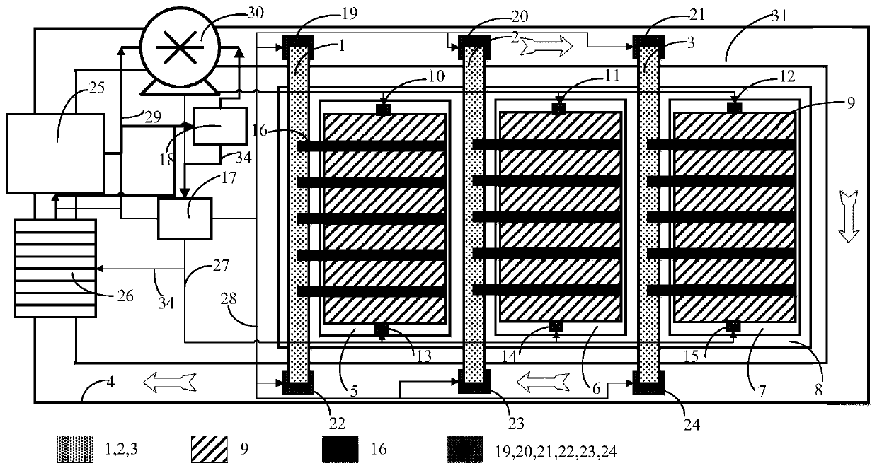
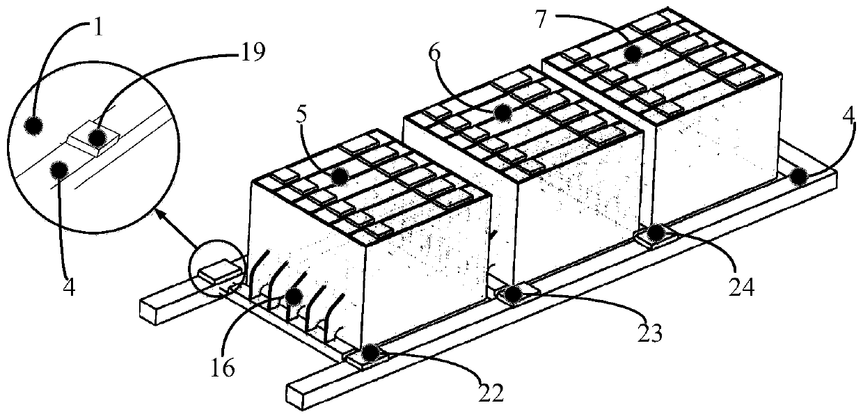
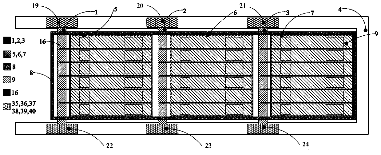
[0049] The embodiment of the present invention discloses a power battery pack multi-stage heat dissipation system and control method based on planar heat pipes, liquid cooling, and phase-change energy storage heat conduction plate coupling. It is used in the emergency power battery pack system of high-speed trains and can ensure The emergency power battery pack system of the group is in the optimal temperature range during operation.

[0050] The following will clearly and completely describe the technical solutions in the embodiments of the present invention in conjunction with the accompanying drawings in the embodiments of the present invention. Obviously, the described embodiments are only some embodiments of the present invention, not all examples. Based on the embodiments of the present invention, other embodiments obtained by persons of ordinary skill in the art without making creative efforts all belong to the protection scope of the present invention.

[0051] like f...


PUM


Abstract

The invention discloses a power battery pack multi-stage heat dissipation system and control method based on coupling of a planar heat pipe, liquid cooling and a phase change energy storage heat conduction plate. The system comprises an electrical system and a cooling system. The electrical system includes a battery module, a temperature sensor, a battery management system, a power supply wire harness, a storage battery and a multi-stage heat dissipation refrigerator control wire. The cooling system comprises multi-stage heat dissipation refrigerators, the phase change energy storage heat conduction plate, the planar heat pipe, a circulating water pipe, a radiator, a water tank, a water pump, and a cooling liquid. A temperature sensor is used to collect the temperature of the battery module and is connected to the battery management system. The water pump, the plurality of multi-stage heat dissipation refrigerators, and the radiator are connected to the storage battery, and the storagebattery provides energy. The water pump, the plurality of multi-stage heat dissipation refrigerators and the radiator are connected to the battery management system through a water pump control wireharness, a multi-stage heat dissipation refrigerator control wire harness and a radiator control wire harness, and are controlled by the battery management system in real time to control overall temperature rise of a power battery pack.

Description

technical field [0001] The invention relates to the technical field of power battery pack heat dissipation systems for rail transit equipment, in particular to a power battery pack multi-stage heat dissipation system and control method based on the coupling of planar heat pipes, liquid cooling, and phase-change energy storage heat conducting plates. Background technique [0002] Due to the failure of the power supply system (including AC high-voltage network and DC catenary), man-made (terrorist) sabotage, accidental factors, natural disasters, etc., the train power supply of rail transit in major cities around the world is interrupted for a short time or paralyzed for a long time. occur. The recovery time of the accident that the train cannot receive electricity normally due to non-vehicle reasons is relatively long, often exceeding the emergency power supply time of the vehicle. Therefore, considering the current operating situation, if the train can realize emergency tra...

Claims


Application Information

Patent Timeline
Patent Type & Authority Applications(China)
IPC IPC(8): H01M10/613H01M10/617H01M10/625H01M10/635H01M10/653H01M10/6552H01M10/6554H01M10/6556H01M10/6567H01M10/659B60L58/26
CPCY02E60/10Y02T10/70
Inventor 徐晓明唐伟孙旭东
Owner JIANGSU UNIV
Learn More