Battery heat management device

A battery thermal management and heat dissipation device technology, applied in battery/fuel cell control devices, secondary batteries, circuits, etc., can solve the problems of unpowered drainage, environmental pollution, waste of phase change materials, etc., and achieve a good working temperature Environmental protection, saving phase change materials, and prolonging the service life

Inactive Publication Date: 2019-05-31
CHONGQING JIAOTONG UNIVERSITY
View PDF12 Cites 6 Cited by
  • Summary
  • Abstract
  • Description
  • Claims
  • Application Information

AI Technical Summary

Problems solved by technology

[0005] The existing battery thermal management system uses the vaporization of low-boiling point phase-change materials to absorb the heat generated by the battery to reduce the operating temperature of the battery. Low-boiling point phase-change materials can indeed achieve a good heat dissipation effect on the battery, but Since the existing battery thermal management system does not have a corresponding recovery device for the vaporized phase change material, a large amount of phase change material will be wasted during cooling, causing environmental pollution and high cost, and the cooling system itself is also A large amount of phase change materials needs to be stored, which also increases the cost. When the battery is discharged at high power, the heat dissipation efficiency cannot meet the requirements; the invention patent with the patent publication number of CN 105552476A discloses a battery pack thermal management system, which solves the problem of battery pack The heat dissipation problem is also very cost-saving, but there are still some problems: the box-type substation material used for cooling cannot achieve unpowered drainage, and it needs to be filled with a liquid of the same height as the battery to ensure the heat dissipation effect; the cooling effect of the top plate condensation plate is limited, Taking air cooling as an example, the contact area between the cold air and the condensation plate is limited; the heat conduction effect of the liquid in the liquid cooling plate is far less than that of the capillary copper tube group, and the evaporation speed is relatively slow under the same conditions, and the heat dissipation effect is poor; the condensation area of ​​the liquid top plate, The backflow method and confluence area are limited and the heat dissipation effect is not good; when the phase change coolant in the cavity shakes violently during driving, it is easy to enter between the upper roof plate and the condensation plate in large quantities, resulting in a decrease in the liquid level in the cooling tank. Affect cooling effect

Method used


Image

  • Battery heat management device
  • Battery heat management device
  • Battery heat management device

Examples


Embodiment Construction

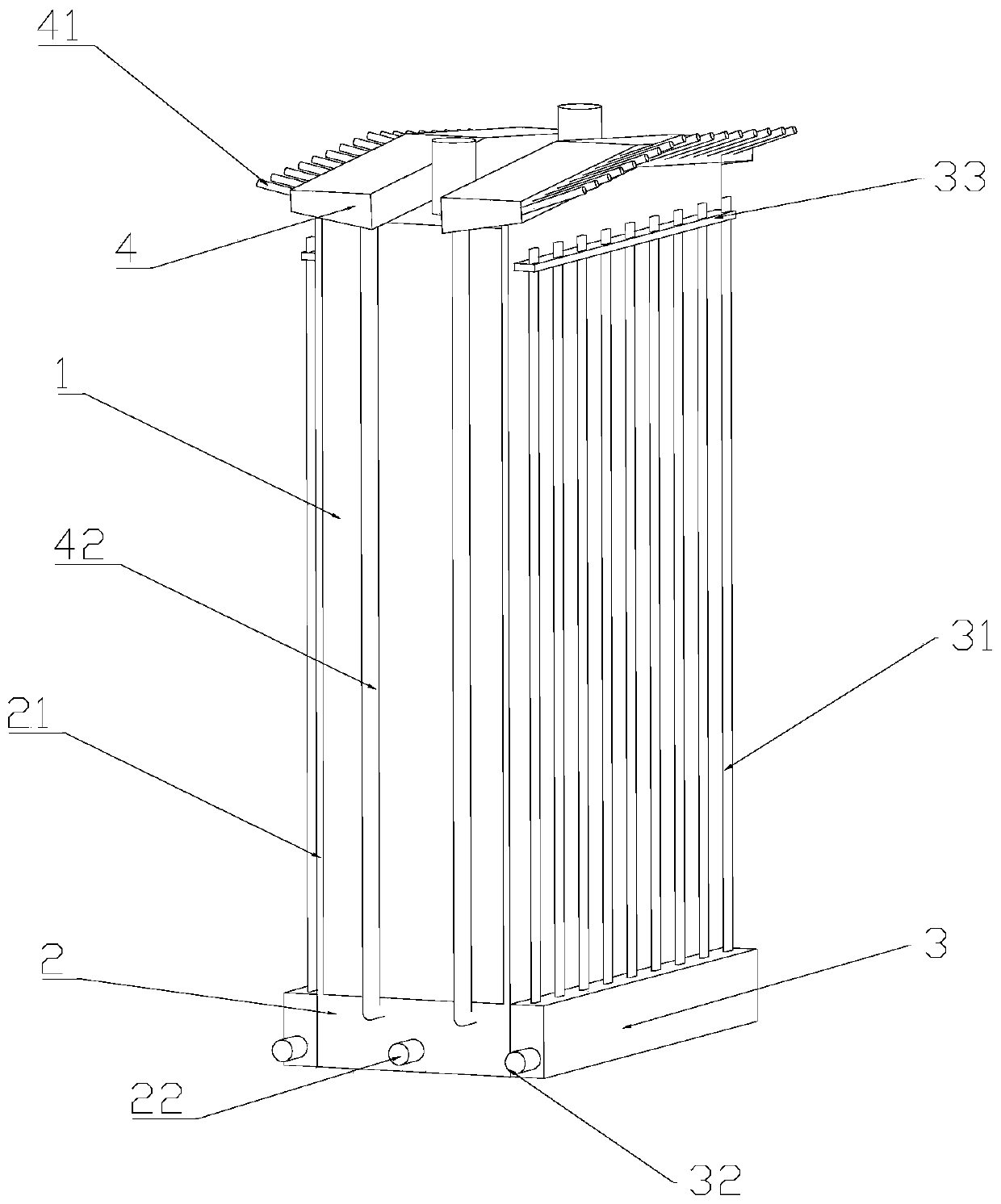
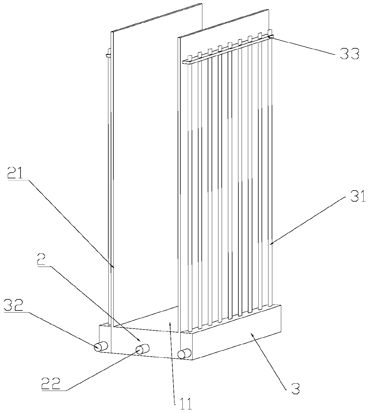
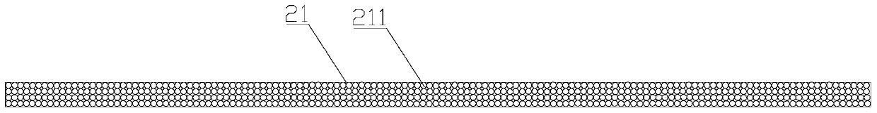
[0025] figure 1 Is a schematic diagram of the overall structure of the present invention, figure 2 Is a schematic diagram of the structure of the heat dissipation assembly of the present invention, image 3 Is a schematic diagram of the structure of the thermally conductive side plate of the present invention, Figure 4 It is a schematic diagram of the structure of the recovery device of the present invention, Figure 5 for figure 1 As shown in the figure, the battery thermal management device in this embodiment includes a first heat dissipation device and a second heat dissipation device. The first heat dissipation device includes a thermally conductive side plate 21 that is thermally conductively attached to the surface of the battery 1 and is vertically arranged The capillary tube 211 inside the heat conducting side plate 21 and the liquid storage bin 2 fixed to the heat conducting side plate 21 and located at the bottom of the heat conducting side plate 21. The liquid storag...


PUM


Abstract

The invention discloses a battery heat management device which comprises first and second heat radiation devices. The first heat radiation device comprises a heat conducting side plate applied to thesurface of the battery, capillary tubes vertically arranged in the heat conducting side plate, and a liquid storage chamber positioned in the bottom of the heat conducting side plate, the liquid storage chamber contains a phase-transition material, and the capillary tubes are communicated to the phase-transition material in the liquid storage chamber; and the second heat radiation device is used to cool the battery or/and the heat conducting side plate in a forced way. According to the disclosed battery heat management device, the capillary tubes and water absorption fibers needless of power for drainage are used to take away heat from the battery for multiple times, the phase-transition material is saved, the environment is protected, and influence on a heat radiation effect when a lot ofphase transition materials contained in the cavity shake and do not make fully contact with the heat conducting side plate can be avoided; and the temperature difference in the battery and between different batteries can be balanced rapidly, heat accumulation is reduced, the service life of the battery is prolonged and a good work temperature environment is provided for the battery.

Description

Technical field [0001] The invention relates to the field of electric vehicle batteries, in particular to a battery thermal management device. Background technique [0002] With the diversification of the automobile industry and the increasingly severe environmental problems, the new energy automobile industry is developing rapidly. Among them, electric vehicles have a smaller environmental impact than traditional vehicles and are used more and more widely. Electric vehicles are powered by on-board power supplies. , Use motors to drive wheels to drive vehicles that meet the requirements of road traffic and safety regulations. As the heart of electric vehicles, batteries are the key to the development of the electric vehicle industry. In addition to the battery’s cruising range, which is the bottleneck for the development of electric vehicles, battery safety issues It should not be underestimated. [0003] The battery management system is an important link that connects the vehicle...

Claims


Application Information

Patent Timeline
Patent Type & Authority Applications(China)
IPC IPC(8): H01M10/613H01M10/617H01M10/625H01M10/6552H01M10/6554B60L58/26
CPCY02E60/10Y02T10/70
Inventor 张甫仁林爱桢张顺飞
Owner CHONGQING JIAOTONG UNIVERSITY
Why Eureka
Try Eureka