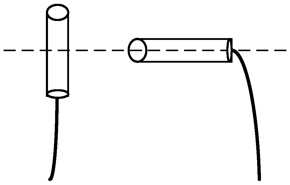
Metal pipeline defect positioning detecting device and method based on magnetic collecting surface scanning
A technology for positioning detection devices and metal pipes, which is applied in the direction of optical testing for flaws/defects, material magnetic variables, etc. It can solve the problems of short service life of device sensors, low spatial resolution, and insufficient safety, and achieve anti-electromagnetic interference capabilities Strong, improved vertical spatial resolution, high sensitivity
- Summary
- Abstract
- Description
- Claims
- Application Information
AI Technical Summary
Problems solved by technology
Method used
Image
Examples
Embodiment 1
[0047] The present embodiment provides a kind of 1. metal pipeline defect localization detection device based on magnetic collecting surface scanning, such as figure 1 As shown, the device includes:
[0048] Permanent magnet 2, optical fiber magnetic sensitive probe array 3, signal connecting optical cable 5, sensing light source module 7 and photoelectric conversion module 8; the light source output by sensing light source module 7 is transmitted to optical fiber magnetic sensitive probe array 3 through signal connecting optical cable 5, optical fiber The return light output by the magnetic sensitive probe array 3 is transmitted to the photoelectric conversion module 8 through the signal connection optical cable 5;
[0049]The permanent magnet 2 includes at least one first permanent magnet 21 and a second permanent magnet 22. The two ends of the two permanent magnets 2 are placed oppositely with the same polarity. By adjusting the magnetic field strength and the spacing dista...
Embodiment 2
[0062] This embodiment has the same inventive concept as Embodiment 1, and provides a metal pipeline defect location detection method based on magnetic collecting surface scanning. The method includes an optical data collection step and a defect detection step.
[0063] Further, the optical data collection step includes the following steps:
[0064] S01: At least one first permanent magnet 21 and second permanent magnet 22 included in the permanent magnet 2 are placed oppositely with the same polarity to form a magnetic collecting surface, and the metal pipeline 4 to be tested is scanned with the magnetic collecting surface;
[0065] S02: The optical fiber magnetic sensitive probe array 3 located between the first permanent magnet 21 and the second permanent magnet 22 receives the input light, and the input light passes through the optical fiber collimator 31, polarizer 32, magneto-optic crystal 33, analyzer and The return light is output after the reflector;
[0066] Further...
PUM
 Abstract
Description
Claims
Application Information
 - R&D
- Intellectual Property
- Life Sciences
- Materials
- Tech Scout
- Unparalleled Data Quality
- Higher Quality Content
- 60% Fewer Hallucinations
Browse by: Latest US Patents, China's latest patents, Technical Efficacy Thesaurus, Application Domain, Technology Topic, Popular Technical Reports.
© 2025 PatSnap. All rights reserved.Legal|Privacy policy|Modern Slavery Act Transparency Statement|Sitemap|About US| Contact US: help@patsnap.com


