A processing technology of ceramic tile grinding tool with iron bottom

A technology of iron and grinding tools, which is applied in the direction of metal processing equipment, grinding devices, manufacturing tools, etc. It can solve the problems of non-standard grinding tooth size, gaps that cannot meet the requirements, and non-standard grinding tooth size. Easy to remove teeth, uniform force, high connection strength

Active Publication Date: 2020-08-14
ZHANGJIAJIE INST OF AERONAUTICAL ENG
View PDF6 Cites 0 Cited by
  • Summary
  • Abstract
  • Description
  • Claims
  • Application Information

AI Technical Summary

Problems solved by technology

[0017] The analysis is as follows: the size difference of the grinding teeth. The grinding teeth are sintered by a metal sintering machine. After the formula alloy powder is stirred evenly, it is pressed and formed by a press, and then sintered by a graphite mold. The size of the grinding teeth is pressed and formed by a press It is still very standard, but the firing is fired at high temperature and high pressure, usually the sintering temperature is 750°C~800°C, the pressure is N×1000000Pa, N is between 5 and 20, that is, the pressure during sintering is 5 to 20 Between the atmospheric pressure, the size of the sintered grinding teeth is not very standard.
[0018] During welding, due to the limitation of the gap between the grinding teeth 1 and the grinding teeth 1, the last piece is often reached, and the size cannot be controlled. We can only heat the grinding teeth according to the remaining size, and use a vise to clamp off the excess part. After welding, it should be noted that there needs to be a gap between the grinding teeth, but the gap has a size limit, between 1~3mm, because the gap reservation is a manual operation, it is not very standard, and through The machine makes the welding area of ​​each grinding tooth. When welding again, it is difficult to implement because the size of the grinding teeth is not standard and the gap does not meet the requirements.

Method used


Image

  • A processing technology of ceramic tile grinding tool with iron bottom
  • A processing technology of ceramic tile grinding tool with iron bottom
  • A processing technology of ceramic tile grinding tool with iron bottom

Examples


Embodiment Construction

[0064] The applicant explains the ceramic tile grinding tool with iron bottom and its production process with reference to the accompanying drawings.

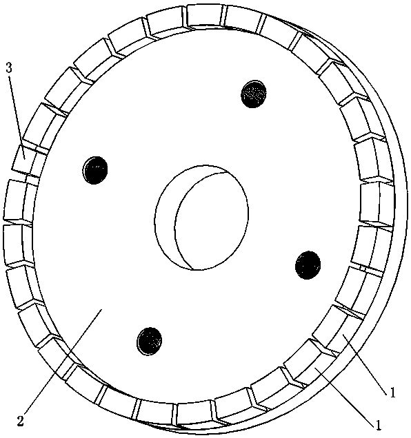
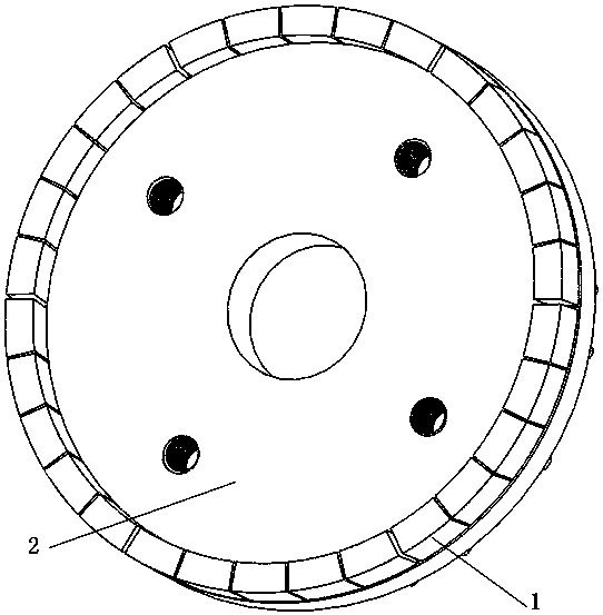
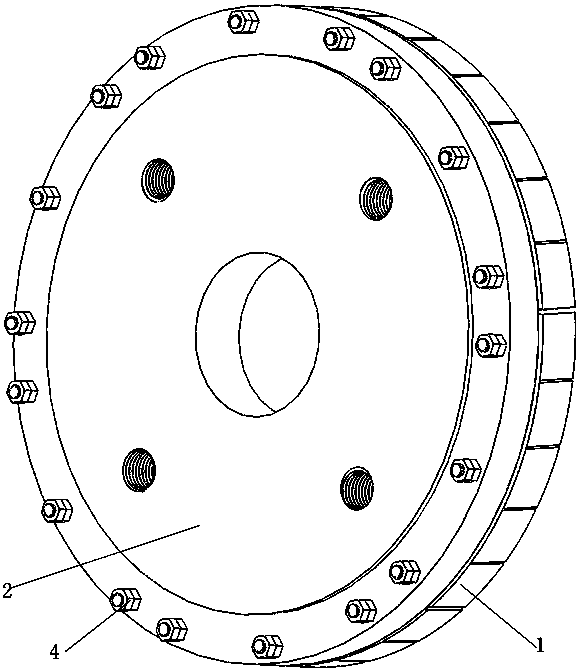
[0065] In the accompanying drawings, 1 is a grinding tooth, 2 is a metal disc, 3 is a half grinding tooth, 4 is a nut, 121 is a threaded hole, 122 is a recessed position, 11 is a screw rod, 12 is an iron bottom, and 13 is an iron sheet , 123 is the clearance position, 21 is the screw hole, 22 is the limiting edge, 23 is the recessed position, 24 is the threaded hole, 25 is the center hole, 26 is the recessed position, 5 is the alloy steel mold, 6 is the gray cast iron mold, 7 Is molding die, and 71 is screw hole, and 72 is notch, and 8 is extrusion mould, and 81 is pressure outlet, and 9 is bottom die, and 91 is screw hole.

[0066] The applicant lists the existing ceramic tile grinding tools for the convenience of understanding the design ideas of this application, and the attached figure 1 It is a schematic diagram of the st...


PUM

PropertyMeasurementUnit
thicknessaaaaaaaaaa
thicknessaaaaaaaaaa
thicknessaaaaaaaaaa

Abstract

The invention relates to a production technology of a ceramic tile grinding tool with an iron bottom. The ceramic tile grinding tool with the iron bottom adopts a sintered grinding head and uses screws and nuts to lock the grinding head to a metal plate, grinding teeth (1), the screws (11) and the iron bottom (12) are sintered together, then the sintered grinding head is locked by the nuts, and aproduction technology of welding the grinding teeth is not adopted. The ceramic tile grinding tool produced by the production technology is high in grinding tooth connection strength, difficulty in tooth removal, uniform in distribution of the grinding teeth, uniform in stress during grinding and small in vibration of a grinding machine, expensive silver-zinc welding pieces are not needed, and thecost is saved; and time-consuming production technologies such as acid washing, water washing and air drying which are harmful to human health are not adopted, and over-welding is eliminated.

Description

technical field [0001] The invention belongs to the processing technology of grinding and polishing products, in particular to a production technology of ceramic tile abrasive tools. Background technique [0002] At present, in the grinding of ceramic tiles, the rough grinding process adopts such as figure 1 One of the abrasive tools shown in the attached figure 1 Among them, the size of the half grinding tooth 3 is obviously smaller than that of the grinding tooth 1, and there is a gap between the grinding tooth 1 and the grinding tooth 1, and between the half grinding tooth 3 and the grinding tooth 1. The half grinding tooth 3 shown in Figure 1 The gap between the grinding tooth 1 and the grinding tooth 1 is not equal to the gap distance between the grinding tooth 1 and the grinding tooth 1, and in the actual product, the gap distance between the grinding tooth 1 and the grinding tooth 1 is not equal, the reason why This phenomenon is related to the sintering process and...

Claims


Application Information

Patent Timeline
Patent Type & Authority Patents(China)
IPC IPC(8): B24D18/00B22F7/08B22F3/10
Inventor 陈立陈胜迁宋新华邓春丽龚航汪风珍
Owner ZHANGJIAJIE INST OF AERONAUTICAL ENG
Why Eureka
Try Eureka