

Capacitor test circuit
A technology of capacitance testing and discharging circuit, applied in the direction of measuring resistance/reactance/impedance, measuring device, measuring electrical variables, etc., can solve the problems of poor anti-interference ability, low test accuracy, low safety, etc. The effect of improving accuracy and safety, eliminating test errors
- Summary
- Abstract
- Description
- Claims
- Application Information
AI Technical Summary
Problems solved by technology
Method used
Image

Examples
Embodiment Construction
[0027] In order to make the objectives, technical solutions and advantages of the present invention clearer, the following further describes the present invention in detail with reference to the accompanying drawings and embodiments. It should be understood that the specific embodiments described herein are only used to explain the present invention, but not to limit the present invention. In addition, the technical features involved in the various embodiments of the present invention described below can be combined with each other as long as they do not conflict with each other.
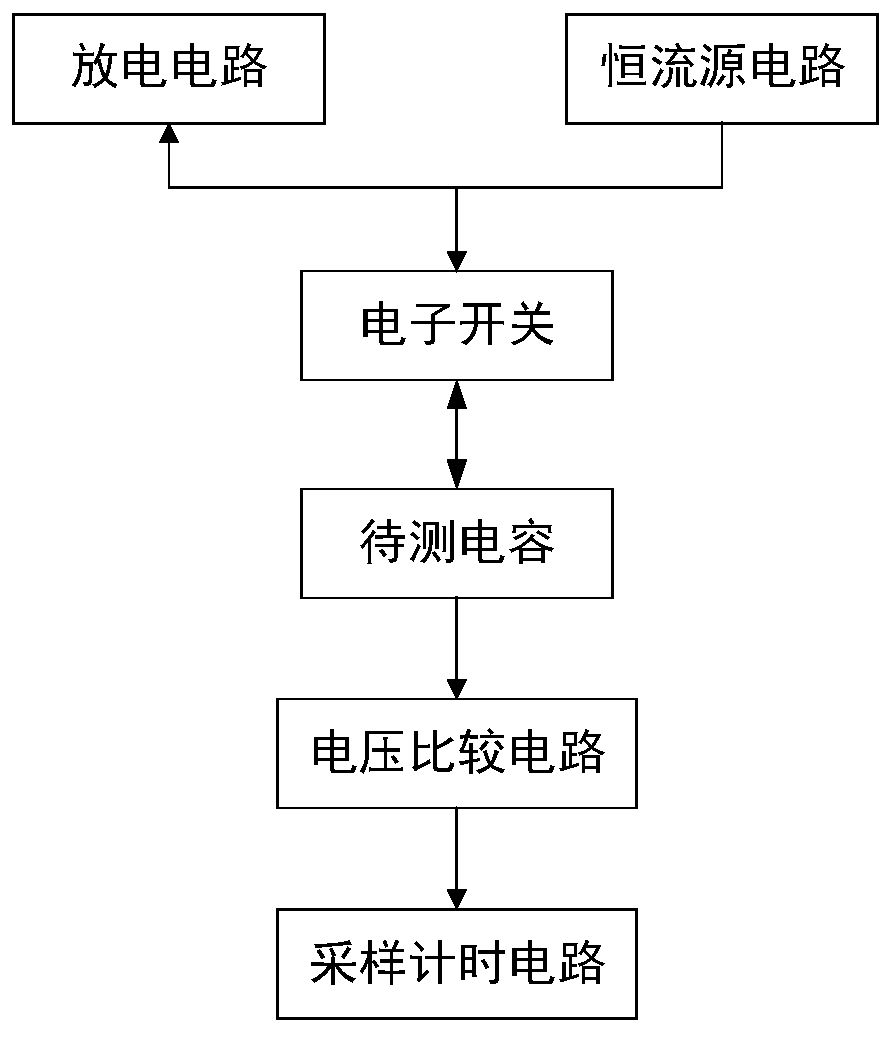
[0028] figure 1 Is a logical block diagram of a capacitance test circuit provided by an embodiment of the present invention, such as figure 1 As shown, the capacitance test circuit includes an electronic switch, a discharge circuit, a constant current source circuit, a voltage comparison circuit, and a sampling timing circuit;
[0029] The electronic switch is used to connect the capacitor under test wit...
PUM
 Abstract
Description
Claims
Application Information