Modular foundation slope radar monitoring system

A monitoring system and modular technology, applied in radio wave measurement systems, measuring devices, instruments, etc., can solve the problems of poor upgrade and expansion ability, inconvenient installation and use, and cumbersomeness, and achieve strong upgrade and expansion ability, convenient disassembly and installation, Easy to install and use

Pending Publication Date: 2019-06-07
CHONGQING UNIV
View PDF0 Cites 10 Cited by
  • Summary
  • Abstract
  • Description
  • Claims
  • Application Information

AI Technical Summary

Problems solved by technology

[0005] These radars have the following problems in actual use: (1) The radar imaging time is slow, and the ground-based real-aperture slope radar uses a servo system to rotate the large-aperture antenna (parabolic antenna) to realize beam scanning, and the scanning speed is very slow; The mobile antenna on the guide rail is equivalent to a virtual large-aperture antenna to realize beam scanning, and the scanning speed is slow; (2) The ability to upgrade and expand is poor, and the angular resolution of the real-aperture slope radar on the ground is δθ a =λ / D, the azimuth resolution at distance R is δR a =(λ / D)R, where λ is the radar wavelength and D is the antenna aperture
If you want to improve the azimuth resolution, you need to increase the size D of the antenna, and the large antenna and the corresponding servo control system are very difficult to manufacture, and it is inconvenient to use. It cannot be installed on a mobile platform, and it is also very difficult to rotate and scan; Assuming that the aperture of the ground-based synthetic aperture radar transceiver antenna is D and the track length is L, the angular resolution of the ground-based synthetic aperture slope radar is δθ a =λ / (2·L), the azimuth resolution at distance R is δR a =(λ / 2L)R, if the azimuth resolution is to be improved, the track length L needs to be increased, and the maximum effective synthetic aperture length L max =(λ / D)R, the resolution is δR a =D / 2, if you want to further improve the resolution, only reduce the aperture D of the unit antenna, so that the gain of the antenna is reduced, and the signal-to-noise ratio of the radar echo will be reduced
(3) The penetration ability of vegetation is poor. The ground-based real-aperture slope radar SSR works in the X-band, and the ground-based synthetic aperture slope radar works in the Ku-band. These radars are not suitable for measuring slopes covered by vegetation; (4) Installation Inconvenient to use, the traditional ground-based solid aperture slope radar antenna is large in size, and the traditional ground-based synthetic aperture radar has a long track, which is relatively cumbersome, inconvenient to carry and transport, unable to quickly arrive at the site, and the time interval from layout and installation to putting into use is long

Method used


Image

  • Modular foundation slope radar monitoring system
  • Modular foundation slope radar monitoring system
  • Modular foundation slope radar monitoring system

Examples


Embodiment Construction

[0014] The preferred embodiments of the present invention will be described in detail below with reference to the accompanying drawings.

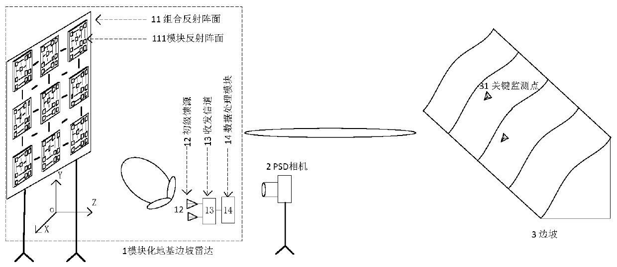
[0015] figure 1 It is a system structure diagram of the present invention. It consists of a modular ground-based slope radar 1, a PSD camera 2, and a slope 3; the modular ground-based slope radar 1 is composed of a combined reflective array 11, a primary feed 12, a transceiver channel 13, and a data processing module 14, and the combined reflective array The surface 11 is formed by splicing several modular reflection fronts 111 ; the PSD camera 2 is used to combine the profiles of the reflection fronts 11 . The primary feed source 12 radiates electromagnetic waves, irradiates the combined reflection front 11, forms a high-gain pencil-shaped beam in a specified direction, performs fast electrical scanning on the slope 3 and key monitoring points 31, and receives echo signals. After passing through the transceiver channel 13, The data is se...


PUM


Abstract

The invention discloses a modular foundation slope radar monitoring system, which consists of a modular foundation slope radar, a PSD camera and a slope, wherein the modular foundation slope radar iscomposed of a combined reflective array surface, a primary feed source, a transmitting and receiving channel and a data processing module, the combined reflective array surface is formed by splicing aplurality of modular reflective array surfaces, and each modular reflective array surface is composed of more than three non-collinear feature light spots and a plurality of basic reflection units; the PSD camera is used for quickly measuring the position coordinates of each basic reflection unit; and the primary feed source radiates electromagnetic waves, irradiates the combined reflective arraysurface, forms a high-gain pencil beam in the specified direction through adjusting the phase compensation of each basic reflection unit, carries out rapid electrical scanning on the slope and key monitoring points, receives an echo signal, transmits the echo signal to the data processing module via the transmitting and receiving channel to obtain a three-dimensional radar image and an interferometric phase diagram and calculates the displacement and deformation of the slope.

Description

technical field [0001] The invention belongs to the technical field of disaster prevention and mitigation, and relates to a modular foundation slope radar monitoring system. Background technique [0002] my country is one of the countries with the most serious geological disasters and the most threatened population in the world. Various landslide disasters (such as open-pit mine side slope landslides, landslides, dam landslides, tailings dam side slope landslides) occur from time to time. Landslides Accidents often cause serious consequences, huge economic losses and heavy casualties. Effective landslide monitoring instruments and equipment are urgently needed to study the trigger mechanism of slope landslides and realize rapid and accurate prediction. [0003] Slope radar uses radar beams to scan the observation area to obtain radar images, and extracts phase change information through image phase interference processing at different times to achieve high-precision measurem...

Claims


Application Information

Patent Timeline
Patent Type & Authority Applications(China)
IPC IPC(8): G01S13/89G01S13/86
Inventor 王韬何秀凤杨朔符依苓于彦涛顾玲榛
Owner CHONGQING UNIV
Why Eureka
Try Eureka