Embedded endfire elements and antennas

An embedded and antenna technology, applied in antenna grounding switch structure connection, suitable for antennas, electrical components and other directions on movable objects, can solve the problem of destroying the aerodynamic characteristics of the projectile surface, not considering the layout of the embedded carrier platform, reducing the Problems such as the stealth performance of the missile body, to achieve the effect of simple structure, low cost, easy production and installation

Active Publication Date: 2020-08-04
CHONGQING UNIV OF POSTS & TELECOMM
View PDF5 Cites 0 Cited by
  • Summary
  • Abstract
  • Description
  • Claims
  • Application Information

AI Technical Summary

Problems solved by technology

[0008] In addition, existing data surveys show that all papers and patents do not consider the layout of the embedded carrier platform, so these antennas will inevitably destroy the aerodynamic properties of the projectile surface and reduce the stealth performance of the projectile, and will also affect the radiation of the antenna field

Method used


Image

  • Embedded endfire elements and antennas
  • Embedded endfire elements and antennas
  • Embedded endfire elements and antennas

Examples


Embodiment 1

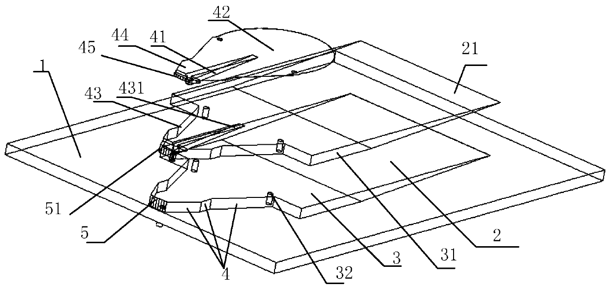
[0065] Such as Figure 1-Figure 6 The configuration of the embedded endfire element shown is:

[0066] Embedded end-fire array element, including waveguide cavity, H-plane horn antenna cavity 4, transition cavity 3, wedge cavity 2,

[0067] The right opening of the waveguide cavity communicates with the small port of the H-plane horn antenna cavity 4, the large port of the H-plane horn antenna cavity 4 communicates with the transition cavity, and the side of the transition cavity away from the H-plane horn antenna cavity 4 communicates with the wedge-shaped cavity;

[0068] The side connecting the wedge-shaped cavity 2 and the transition cavity 3 is a rectangular surface arranged in the vertical direction, the front of the wedge-shaped cavity is a horizontal plane, and the bottom surface of the wedge-shaped cavity is a slope; a wedge-shaped medium with the same shape as the wedge-shaped cavity is embedded in the wedge-shaped cavity Prism 21; the slope of the wedge-shaped cavi...

Embodiment 2

[0078] Such as Figure 4 As shown, preferably, on the basis of the above embodiments, further, the waveguide cavity is a trapezoidal waveguide cavity 5, the trapezoidal waveguide cavity 5 is a cavity structure with a trapezoidal front, and the opening on the right side is where the bottom edge of the trapezoidal front is. The opening at the lower bottom edge of the trapezoidal front communicates with the small port of the horn antenna cavity 4 on the H surface. The design of the trapezoidal waveguide cavity 5 is equivalent to cutting the waveguide cavity into a trapezoidal structure, which improves the working bandwidth of the antenna. At the same time, avoiding the traditional method of inserting multiple metal cylindrical needles into the medium, so that the structure is simple and easy to process.

Embodiment 3

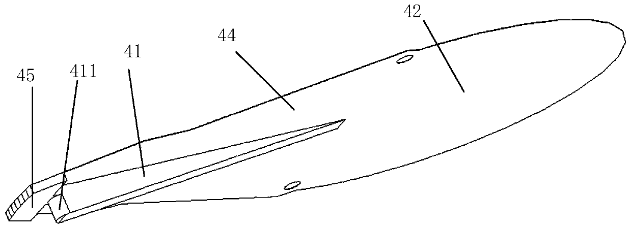
[0080] Such as Figure 4 As shown, preferably, on the basis of the above-mentioned embodiments, further, the extension part B preferably has the following structural shape, the extension part B is an ellipse with a partly elliptical boundary that protrudes naturally, continuously and smoothly from the right end of the antenna radiation patch 44 The elliptical patch 42 includes a part where the right semi-major axis is located and a transition part, and the transition part is located between the right side of the antenna radiation patch 44 and the part where the right semi-major axis is located.


PUM


Abstract

The invention discloses an embedded end-fire array element and an antenna. Three techniques are used in the aspect of improving the bandwidth of the antenna. (1) a trapezoidal waveguide cavity is adopted to realize only a pure TE10 mode appears in an extremely wide frequency band; (2) a smoothly loaded extension part B is formed at the end of a radiation patch, a structure not limited to an elliptical structure is formed, the end current reflection is reduced, and impedance matching is improved; and (3) ridges with exponential cambered surfaces or linear bevels are adopted to form an H-faced horn waveguide structure with ridges, and the TE10 mode can be controlled to work in an extremely wide frequency band range. In order to increase the antenna gains, a low-cost, low-dielectric constantTeflon material is selected as a wedge-shaped dielectric prism, the dielectric constant of the material is 2.2, the thickness is up to 8 mm, the bottom surface has a form of any curve changing from 8mm to 0 mm, and the surface is flush with the surface of a metal carrier. Radiation conversion from TE waves to leaky waves is realized, and the radiation gains of the antenna are improved.

Description

technical field [0001] The invention relates to the field of end-fire antennas, in particular to embedded end-fire array elements and antennas. Background technique [0002] End-fire antenna refers to the antenna whose main beam direction is consistent with the arrangement of the antenna structure or the direction of the extension end. Due to its strong directivity and high gain, it has been widely used on high-speed mobile carrier platforms such as aircraft, missiles, and drones. to develop. However, due to the requirements of the aerodynamic characteristics of the projectile and the stealth performance, it is usually required that the antenna can be embedded in a low profile conformal to the carrier platform. In recent years, broadband, small end-fire antennas / antenna arrays based on high-speed carrier platforms have received a lot of research. There are basically three types of structures: (1) dielectric surface wave antenna. The antenna is made of ceramic material wit...

Claims


Application Information

Patent Timeline
Patent Type & Authority Patents(China)
IPC IPC(8): H01Q1/36H01Q1/50H01Q13/02H01Q1/28H01P3/12H01P3/123
Inventor 王平陈秋作
Owner CHONGQING UNIV OF POSTS & TELECOMM
Why Eureka
Try Eureka