Dynamic voltage regulator and dynamic voltage regulation method

A technology of DC voltage and compensation method, applied in the field of electric power, can solve the problems of high cost, large volume and complex structure, and achieve the effect of fast charging and discharging speed, high energy density and reducing volume

Inactive Publication Date: 2019-06-07
GUANGZHOU POWER SUPPLY BUREAU GUANGDONG POWER GRID CO LTD
View PDF5 Cites 3 Cited by
  • Summary
  • Abstract
  • Description
  • Claims
  • Application Information

AI Technical Summary

Problems solved by technology

However, the existing voltage sag compensation device requires three independent single-phase inverters and an additional c

Method used


Image

  • Dynamic voltage regulator and dynamic voltage regulation method
  • Dynamic voltage regulator and dynamic voltage regulation method
  • Dynamic voltage regulator and dynamic voltage regulation method

Examples


Embodiment Construction

[0049] The present invention will be described in further detail below in conjunction with the accompanying drawings and embodiments. In particular, the following examples are only used to illustrate the present invention, but not to limit the scope of the present invention. Likewise, the following embodiments are only some but not all embodiments of the present invention, and all other embodiments obtained by persons of ordinary skill in the art without creative efforts fall within the protection scope of the present invention.

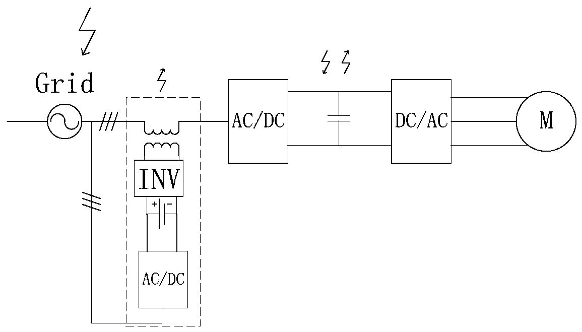
[0050] The invention provides a direct current voltage sag compensation device, which can realize the simple structure, small volume and low cost of the direct current voltage sag compensation device.

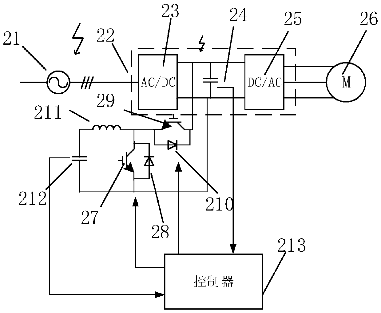
[0051] See figure 2 , figure 2 It is a structural schematic diagram of an embodiment of the DC voltage sag compensation device of the present invention. Such as figure 2 As shown, the DC voltage sag compensation device 20 includes: a first swit...


PUM


Abstract

The invention discloses a dynamic voltage regulator, a controller and a dynamic voltage regulation method. The dynamic voltage regulator comprises a first switch transistor, a first switch transistorantiparallel diode, a second switch transistor, a second switch transistor antiparallel diode, an inductor, a supercapacitor group and the controller. The first switch transistor and the first switchtransistor antiparallel diode are connected in parallel. The second switch transistor and the second switch transistor antiparallel diode are connected in parallel. The supercapacitor group is taken as an energy storage unit. The inductor, the first switch transistor, the antiparallel diode thereof, the second switch transistor, and the antiparallel diode thereof form a bidirectional DC/DC topology circuit for charge/discharge, and bidirectional energy flow is realized. In the mode, the dynamic voltage regulator is simple in structure, small in size and low in cost.

Description

technical field [0001] The invention relates to the field of electric power technology, in particular to a DC voltage sag compensation device and a DC voltage sag compensation method. Background technique [0002] With the advent of the information age, more and more precision electrical equipment is put into the power grid. It is difficult for these precision equipment to work normally within a large voltage range. Therefore, it is particularly important to suppress the drop of the load supply voltage. An existing measure to suppress voltage sag is to install compensation equipment on the load side, and installing a DVR (Dynamic Voltage Regulator, DC voltage sag compensation device) on the load side is currently one of the most effective measures to balance the load voltage. [0003] See figure 1 , figure 1 It is a structural schematic diagram of an existing voltage sag compensation device. Such as figure 1 As shown, the voltage sag compensation device includes an energ...

Claims


Application Information

Patent Timeline
IPC IPC(8): H02M3/158H02J7/34
Inventor 马智远莫文雄许中王勇栾乐刘伟明周凯吴国玥李智宁郭倩雯李情黄伟钊
Owner GUANGZHOU POWER SUPPLY BUREAU GUANGDONG POWER GRID CO LTD
Why Eureka
Try Eureka