A segmented protection device for drill pipe

A protection device, segmented technology, applied to drill pipes, drill pipes, drilling tools, etc., can solve the problems of high cost of drill pipe protection sleeves, inability to disperse well, and easy damage of protection sleeves, etc. Drying effect, reducing pressure, reducing the effect of soil squeezing force

Active Publication Date: 2020-09-22
CHENGDU KESHENG PETROLEUM TECH
View PDF6 Cites 0 Cited by
  • Summary
  • Abstract
  • Description
  • Claims
  • Application Information

AI Technical Summary

Problems solved by technology

[0005] The invention provides a segmented protection device for drill pipes, which solves the problems caused by the high cost of the traditional drill pipe protection sleeve, difficult maintenance, poor universality and inability to well disperse the sudden increase of soil extrusion force. The problem that the protective sleeve is easily damaged

Method used


Image

  • A segmented protection device for drill pipe
  • A segmented protection device for drill pipe
  • A segmented protection device for drill pipe

Examples


Embodiment 1

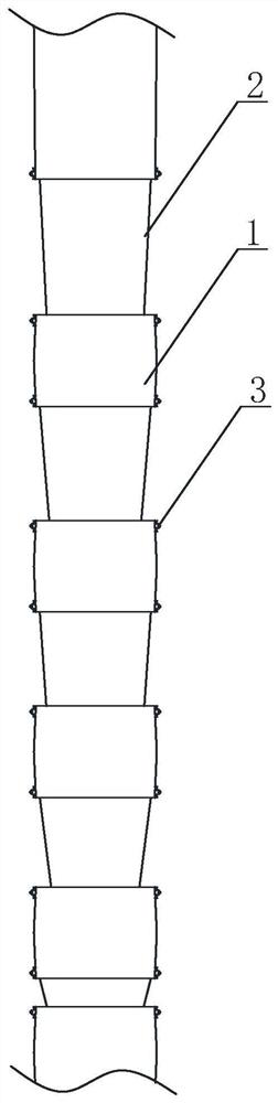
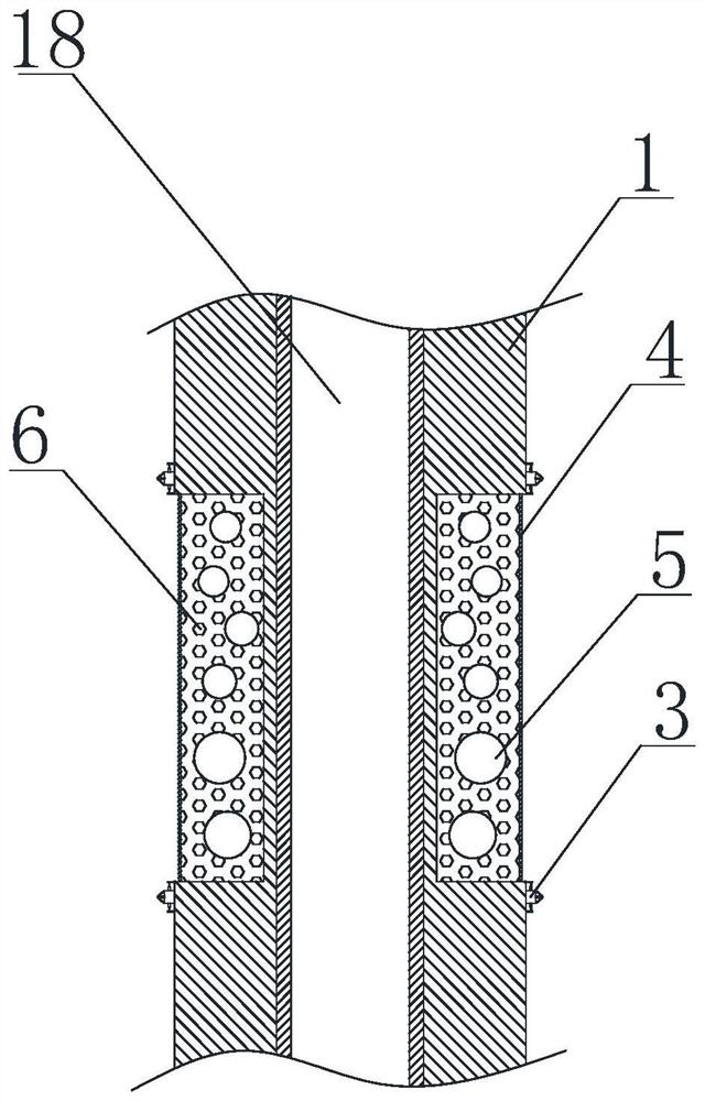
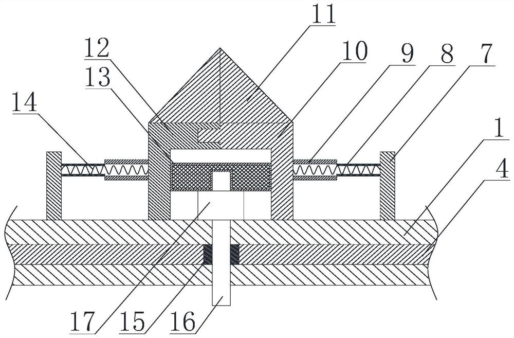
[0033] Such as Figure 1 to Figure 3 As shown, a segmented protection device for drill rods in the present invention includes a cylinder body 1, and a plurality of annular grooves are arranged on the cylinder body 1, and the generatrices of the annular grooves and the generatrix of the cylinder body 1 Coaxial, the annular groove divides the cylinder body 1 into a plurality of rigid parts, and the flexible part 2 is arranged in the annular groove. Along the direction from the middle of the rigid part to the flexible part 2, the thickness of the rigid part gradually decreases. In the direction from the upper end of the cylinder 1 to the lower end of the cylinder 1, the height of the flexible part 2 gradually decreases; the flexible part 2 includes a leather layer 4, and the top of the leather layer 4 is placed in a notch on the upper surface of the annular groove. The bottom is placed in the notch on the lower surface of the annular groove, a plurality of fixing rings 15 are arr...

Embodiment 2

[0036] Such as Figure 1 to Figure 3As shown, a segmented protection device for drill rods includes a cylinder body 1 on which a plurality of annular grooves are arranged, and the generatrix of the annular grooves is coaxial with the generatrix of the cylinder body 1 , the annular groove divides the cylinder body 1 into a plurality of rigid parts, and a flexible part 2 is arranged in the annular groove. Along the direction from the middle of the rigid part to the flexible part 2, the thickness of the rigid part gradually decreases. 1 from the upper end to the lower end of the barrel 1, the height of the flexible part 2 gradually decreases; the flexible part 2 includes a leather layer 4, the top of the leather layer 4 is placed in the notch on the upper surface of the annular groove, and the leather layer 4 The bottom is placed in the notch on the lower surface of the annular groove, a plurality of fixing rings 15 are arranged on the top and bottom of the leather layer 4, and a...


PUM


Abstract

A segmented protection device for a drill pipe comprises: a cylindrical body (1), wherein multiple annular grooves are arranged on the cylindrical body (1), the annular grooves divide the cylindrical body (1) into multiple rigid portions, and flexible portions (2) are arranged in the annular grooves; the flexible portion (2), comprising a leather layer (4), wherein multiple fixed rings (15) are arranged on both a top portion and a bottom portion of the leather layer (4); multiple bolts (16) and nuts (17) matching the bolts (16); an annular filling chamber, wherein the annular filling chamber is filled with multiple first balls (5) and multiple second balls (6), and the diameter of the first ball (5) is 8 to 15 times the diameter of the second ball (6); and multiple protection mechanisms (3), wherein at least one bolt (16) and at least one nut (17) are disposed in the protection mechanisms (3). The compressive strength at different points of the cylindrical body (1) is different, and the addition of the lower-cost flexible portion (2) not only reduces production costs of the cylindrical body (1), but also facilitates transportation and storage steps of the cylindrical body (1). The cylindrical body (1) can be adapted for a variety of soil environments, thereby improving the universality of a protective sleeve.

Description

technical field [0001] The invention relates to the field of petroleum machinery, in particular to a segmented protection device for drill rods. Background technique [0002] The drill pipe is a steel pipe with a threaded tail, which is used to connect the surface equipment of the drilling rig and the drilling and grinding equipment or the bottom hole device at the bottom of the drilling well. As one of the important oil extraction equipment, the drill pipe can transport the drilling mud to the drill bit, and raise, lower or rotate the bottom hole device together with the drill bit. [0003] As the drill pipes are driven into the ground, they must be designed to withstand the enormous pressure from the soil. In order to increase the service life of the drill pipe, reduce the process cost, and prevent the drill pipe from being damaged due to soil extrusion during use, in the prior art, a protective sleeve is usually provided outside the conveying section of the drill pipe. ...

Claims


Application Information

Patent Timeline
Patent Type & Authority Patents(China)
IPC IPC(8): E21B17/00E21B17/10E21B12/00
CPCE21B12/00E21B17/00E21B17/10
Inventor 张远香
Owner CHENGDU KESHENG PETROLEUM TECH
Why Eureka
Try Eureka