
A pgc multi-sensor measurement system using code division multiplexing of pseudo-random codes

A pseudo-random code and multi-sensor technology, which is applied in the field of photoelectric detection, can solve the problems that are not suitable for large-scale multiplexed array applications, cannot be continuously observed by a single sensor, and the accuracy of the limited light source can be adjusted to achieve maximum design flexibility. Good temperature stability and anti-vibration stability, the effect of small changes in the optical path

Active Publication Date: 2021-07-23
HARBIN ENG UNIV
View PDF14 Cites 0 Cited by
  • Summary
  • Abstract
  • Description
  • Claims
  • Application Information

AI Technical Summary

Problems solved by technology

[0007] Space-division multiplexing technology has the advantages of simple structure, easy implementation and no crosstalk, but its transmission efficiency is low, wasting fiber bandwidth resources, and it is not suitable for large-scale multiplexing array applications, and the system cost in remote transmission applications very big
Due to the use of multiple light sources with different wavelengths, the wavelength division multiplexing technology is expensive and limited by the adjustable accuracy of the light source
Time-division multiplexing technology cannot continuously observe a single sensor because of the query operation

Method used


Image

  • A pgc multi-sensor measurement system using code division multiplexing of pseudo-random codes
  • A pgc multi-sensor measurement system using code division multiplexing of pseudo-random codes
  • A pgc multi-sensor measurement system using code division multiplexing of pseudo-random codes

Examples


Embodiment

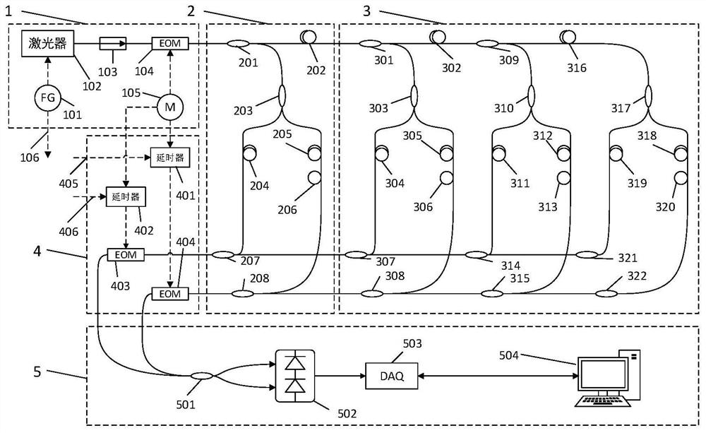
[0076] Implementation example - three-component fiber optic seismometer for shallow wells based on random code multiplexing scheme

[0077] The optical path diagram of the embodiment is as follows figure 1 As shown, the entire optical fiber system includes a highly stable light source and modulation module 1, a sensor measurement module 2, a cascaded sensor array 3, a random code demodulation module 4, and an interference demodulation module 5. Among them, the interference demodulation module is connected to the The PC terminal on land performs demodulation, and the entire seismometer system includes two modules, the sensor measurement module 2 and the sensor cascade array 3, and there are no active components. The highly stable light source and modulation module 1, the random code demodulation module 4 and the interference demodulation module 5 are located on the well, and are separate systems that provide demodulation control over the entire seismometer.

[0078] The overal...


PUM


Abstract

The invention discloses a PGC multi-sensor measurement system using code division multiplexing of pseudo-random codes, which belongs to the technical field of photoelectric detection. The invention includes a narrow line width light source, a code division modulation and demodulation device, a multi-probe array, a photoelectric detector and a post demodulation device. The laser is modulated by an external sinusoidal signal, and the modulated signal is multiplexed by adding a pseudo-random noise code to the EOM. The corresponding signals of the rear sensor sensing array are demultiplexed and then interfered for subsequent PGC demodulation. The present invention is suitable for multiplexing and modulation and demodulation of PGC under the condition of limited space and limited number of cables; it can demodulate the optical interference signals of multiple sensors at the back end in time division, and at the same time, the introduction of random codes can effectively resist Noise and narrow-band noise in the communication link; the demodulation end uses the properties of photodetectors to perform differential detection to eliminate DC noise; it can be used in the production of PGC vibration sensors or as a single-fiber multi-sensor multiplexing solution for optical hydrophones based on PGC technology.

Description

technical field [0001] The invention belongs to the technical field of photoelectric detection, and in particular relates to a PGC multi-sensor measurement system using code division multiplexing of pseudo-random codes. Background technique [0002] The interferometric optical fiber sensor uses the phase change in the optical path to indirectly measure the physical quantity to be measured, including vibration, stress, displacement, speed, etc. This method has the characteristics of high sensitivity, good linearity, small size and large dynamic range. Typical fiber optic sensor applications include fiber optic hydrophones, fiber optic seismometers, fiber optic strain gauges, etc. Fiber-optic seismometers can monitor large-amplitude signals such as earthquakes and nuclear explosions. Optical fiber hydrophones are used to monitor underwater invisible targets and blind areas that cannot be detected by radar. [0003] The phase change in the optical path needs to be solved by ...

Claims


Application Information

Patent Timeline
Patent Type & Authority Patents(China)
IPC IPC(8): G01D5/353
Inventor 杨军张毅博田帅飞邹晨祝海波苑勇贵李寒阳苑立波
Owner HARBIN ENG UNIV
Learn More