Array antenna automatic testing device

An automatic test device and array antenna technology, applied in the antenna radiation pattern and other directions, can solve the problems of high power consumption, high cost, and inability to realize beam shape, etc., and achieve the effects of simplifying complexity, increasing isolation, and improving test accuracy

Pending Publication Date: 2019-06-14
GCI SCI & TECH
View PDF0 Cites 3 Cited by
  • Summary
  • Abstract
  • Description
  • Claims
  • Application Information

AI Technical Summary

Problems solved by technology

[0003] In the prior art, there are mainly two types of array antenna system architectures. (1) The array antenna uses an analog phase shifter to control the feeding phase of each antenna radiating element to realize beam reconstruction of the antenna. The phased array of this architecture Limited antenna flexibility to achieve complex beam shapes
(2) Various algorithms in the digital domain are used to realize beamforming. This system architecture has extremely high flexibility. Each channel requires ADC / DAC to process signals, which has high cost and high power consumption, especially when the system bandwidth is wider. more serious
There are many antennas in the antenna array, such as 64-element array antenna, 128-element array antenna, and 256-element array antenna. Each antenna element corresponds to a radio frequency unit. The radio frequency unit includes radio frequency gain control and phase control functions. Shaped functions, the gain control and phase control in all radio frequency units must be precise, so the test workload for radio frequency units is relatively large

Method used


Image

  • Array antenna automatic testing device
  • Array antenna automatic testing device
  • Array antenna automatic testing device

Examples


Embodiment Construction

[0026] The following will clearly and completely describe the technical solutions in the embodiments of the present invention with reference to the accompanying drawings in the embodiments of the present invention. Obviously, the described embodiments are only some, not all, embodiments of the present invention. Based on the embodiments of the present invention, all other embodiments obtained by persons of ordinary skill in the art without creative efforts fall within the protection scope of the present invention.

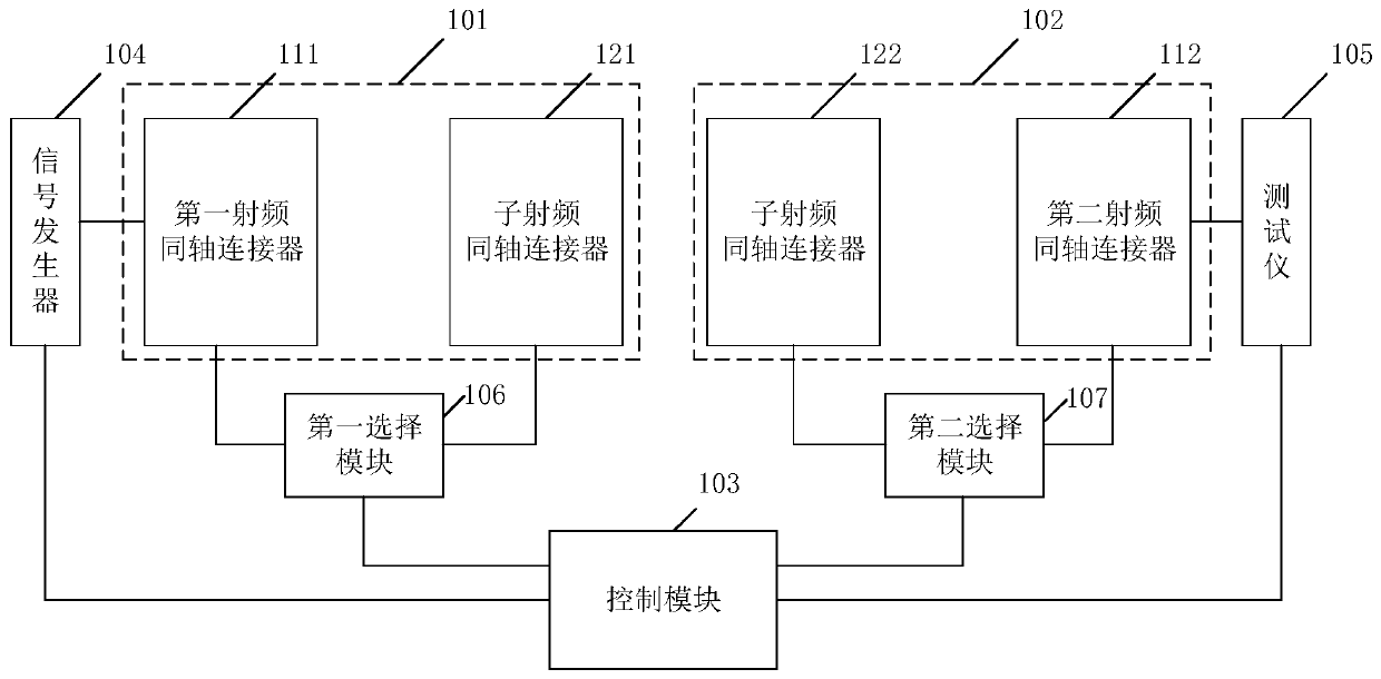
[0027] see figure 1 , is a schematic structural diagram of an array antenna automatic test device provided by an embodiment of the present invention, including: a first radio frequency module 101, a second radio frequency module 102, a signal generator 104 connected to the control module 103, a tester 105, A first selection module 106 and a second selection module 107;

[0028] The first selection module 106 and the second selection module 107 are multiple selecti...


PUM


Abstract

The invention discloses an array antenna automatic testing device. The array antenna automatic testing device testing device is characterized by comprising a first radio frequency module, a second radio frequency module, a signal generator, a tester, a first selection module and a second selection module, wherein the signal generator, the tester, the first selection module and the second selectionmodule are all connected with a control module; one end of a first radio frequency coaxial connector is connected with the fixing end of the first selection module, and one ends of all sub-radio-frequency coaxial connectors of the first radio frequency module are connected with all selection ends of the first selection module correspondingly; one end of a second radio frequency coaxial connectoris connected with the fixing end of the second selection module, and one ends of all sub-radio-frequency coaxial connectors of the second radio frequency module are connected with the all selection ends of the second selection module correspondingly; the signal generator is connected with the other end of the first radio frequency coaxial connector, and the tester is connected with the other end of the second radio frequency coaxial connector. According to the array antenna automatic testing device, the modularization and test automation of array antenna radio frequency front end test can be realized, the consistency of the test is ensured, and testing time is shortened.

Description

technical field [0001] The invention relates to the technical field of array antenna testing, in particular to an array antenna automatic testing device. Background technique [0002] The research and application of array antennas has always been a research hotspot in the field of antennas. Compared with traditional single antennas, array antennas can quickly and flexibly realize the beamforming of the antenna pattern by controlling the feeding phase of each antenna element of the array antenna, so it is widely used. It is used in many fields such as satellite navigation, communication, military affairs, and remote sensing. As the future antenna technology, the active array antenna is an important trend in the design and development of antenna arrays in the future, and it is an important development direction for subsequent antenna system miniaturization, intelligent coverage, and green base stations. [0003] In the prior art, there are mainly two types of array antenna sy...

Claims


Application Information

Patent Timeline
Patent Type & Authority Applications(China)
IPC IPC(8): G01R29/10
Inventor 王东林赵栋黄利麻艳
Owner GCI SCI & TECH
Why Eureka
Try Eureka