A kind of solar cell and its manufacturing method
A technology of solar cells and manufacturing methods, applied in the direction of final product manufacturing, sustainable manufacturing/processing, circuits, etc., can solve the problems of battery performance degradation, restriction of battery efficiency, improvement, etc.
- Summary
- Abstract
- Description
- Claims
- Application Information
AI Technical Summary
Problems solved by technology
Method used
Image
Examples
Embodiment 1
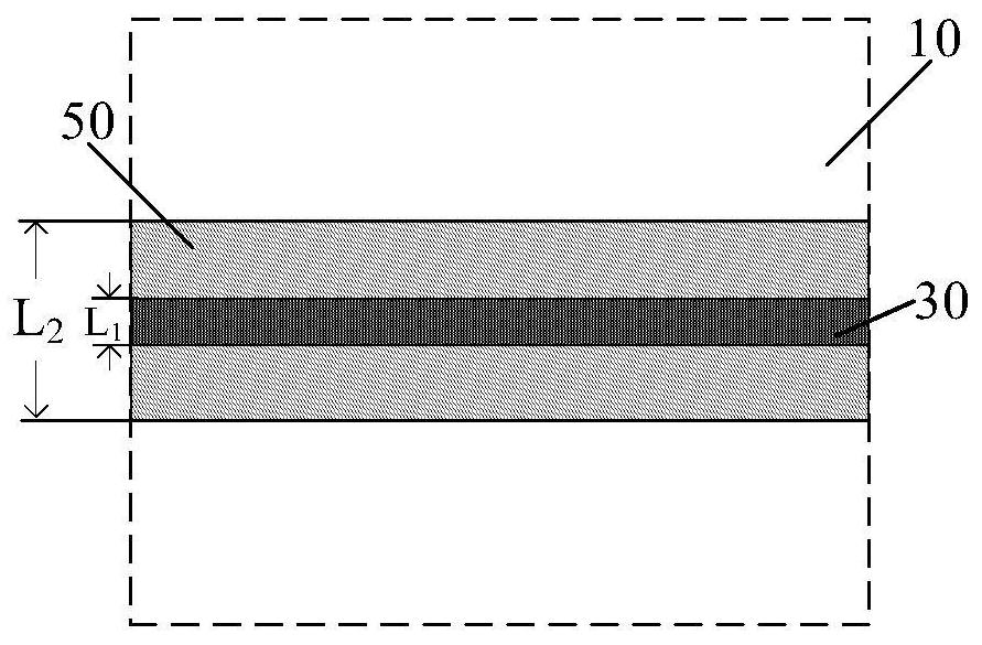
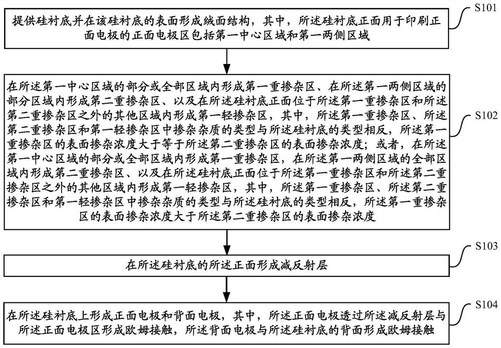
[0059] The invention provides a method for manufacturing solar cells, which is mainly suitable for the production of SE cells. Please refer to figure 2 , figure 2 is a flowchart of a method for manufacturing a solar cell according to a specific embodiment of the present invention. As shown, the manufacturing method includes:
[0060] In step S101, a silicon substrate is provided and a textured structure is formed on the surface of the silicon substrate, wherein the front electrode area on the front side of the silicon substrate for printing front electrodes includes a first central area and first two side areas ;
[0061] In step S102, a first heavily doped region is formed in part or all of the first central region, a second heavily doped region is formed in a part of the first two side regions, and A first lightly doped region is formed in a region other than the first heavily doped region and the second heavily doped region on the front side of the silicon substrate, wh...
Embodiment 2
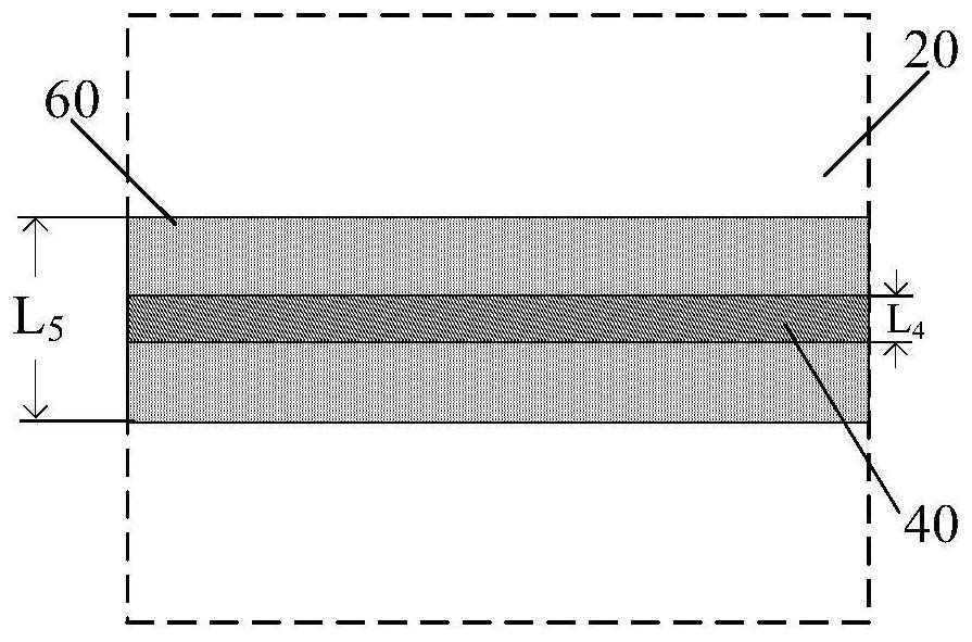
[0087] The invention also provides a solar battery, specifically an SE battery. The solar cell consists of:
[0088] A silicon substrate, the front side of the silicon substrate includes a front electrode area for printing front electrodes, and the front electrode area includes a first central area and first two side areas;
[0089] A first heavily doped region, a second heavily doped region, and a first lightly doped region, the first heavily doped region is formed in part or all of the first central region, the second heavily doped region impurity regions are formed in partial regions of the first two side regions, and the first lightly doped region is formed on the front side of the silicon substrate between the first heavily doped region and the second heavily doped region In other regions, wherein, the type of impurity doped in the first heavily doped region, the second heavily doped region and the first lightly doped region is opposite to the type of the silicon substra...
Embodiment 3
[0108] The invention also provides a solar cell manufacturing method, which is suitable for the production of SE-PERC cells. The manufacturing method includes:
[0109] In step S201, a silicon substrate is provided and a textured structure is formed on the surface of the silicon substrate, wherein the front electrode area on the front side of the silicon substrate for printing front electrodes includes a first central area and first two side areas ;
[0110] In step S202, a first heavily doped region is formed in part or all of the first central region, a second heavily doped region is formed in a part of the first two side regions, and the A first lightly doped region is formed in a region other than the first heavily doped region and the second heavily doped region on the front side of the silicon substrate, wherein the first heavily doped region, the second heavily doped region The type of doping impurities in the double doped region and the first lightly doped region is ...
PUM
 Abstract
Description
Claims
Application Information
 - R&D
- Intellectual Property
- Life Sciences
- Materials
- Tech Scout
- Unparalleled Data Quality
- Higher Quality Content
- 60% Fewer Hallucinations
Browse by: Latest US Patents, China's latest patents, Technical Efficacy Thesaurus, Application Domain, Technology Topic, Popular Technical Reports.
© 2025 PatSnap. All rights reserved.Legal|Privacy policy|Modern Slavery Act Transparency Statement|Sitemap|About US| Contact US: help@patsnap.com


