Detecting module and detecting method for abrasion of cutting edge of diamond tool

A diamond tool and detection module technology, which is applied in the direction of manufacturing tools, metal processing equipment, measuring/indicating equipment, etc., can solve the problems of small scanning range, difficulty in high integration, and difficulty in large-scale wear observation, so as to improve consistency and reliability effect

Active Publication Date: 2019-06-18
CHANGCHUN UNIV OF SCI & TECH
View PDF7 Cites 3 Cited by
  • Summary
  • Abstract
  • Description
  • Claims
  • Application Information

AI Technical Summary

Problems solved by technology

The occurrence of tool wear also affects the machining quality of the workpiece
[0004] The current diamond tool wear detection method is mainly through the atomic force microscope, and the nano-scale scanning of the cutting edge area by the atomic force probe to obtain a three-dimensional image of the cutting edge area, and then judge the degree of tool wear, but the scanning range of the atomic force scanning is small, generally in the It is difficult to achieve large-scale wear observation, and it is difficult to achieve high integration of atomic force measurement equipment on the machine tool, and it is generally used for offline measurement; in addition, optical imaging is also used for diamond tools. Surface measurement, but visible light imaging is limited by the imaging photosensitive chip pixel and photosensitive sensitivity, as well as the existence of detection noise, the measurement reliability of microscopic wear is low, generally used for the measurement of tool wear above the micron level, with the help of other images 3D recovery algorithm, it is difficult to accurately evaluate the wear degree of diamond tools on a 3D scale

Method used


Image

  • Detecting module and detecting method for abrasion of cutting edge of diamond tool
  • Detecting module and detecting method for abrasion of cutting edge of diamond tool
  • Detecting module and detecting method for abrasion of cutting edge of diamond tool

Examples


Embodiment Construction

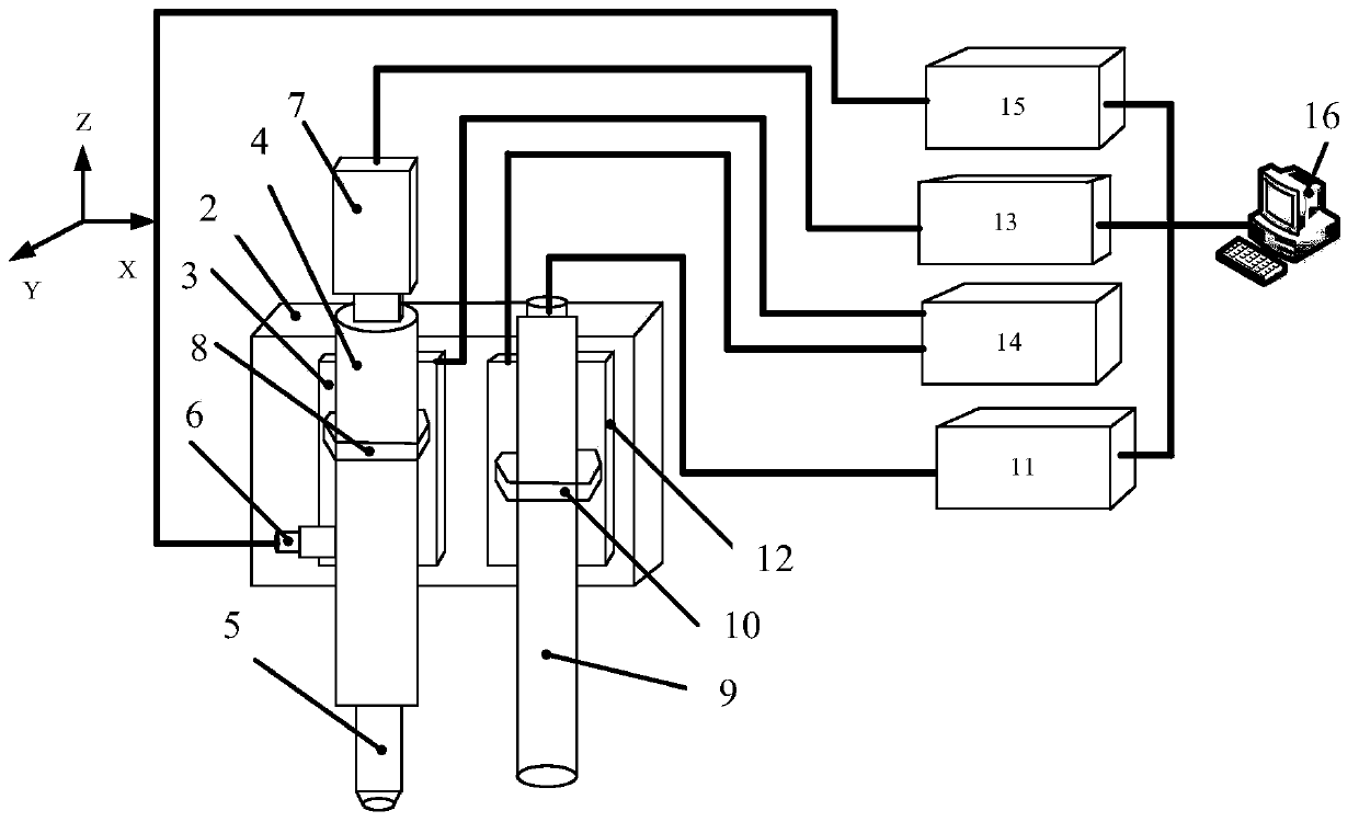
[0037] A diamond tool cutting edge wear detection module, such as figure 1 As shown, it includes 3R high-precision pneumatic conversion fixture 1, adapter plate 2, microscope tube Z-direction motion table 3, single-tube zoom microscope tube 4, microscope objective lens 5, coaxial point light source 6, CCD camera 7, lens tube Fixture 8, spectral confocal sensor 9, spectral confocal sensor fixture 10, spectral confocal controller 11, spectral confocal sensor Z-direction motion table 12, image acquisition card 13, motion controller 14, light source controller 15 and PC processing machine16.

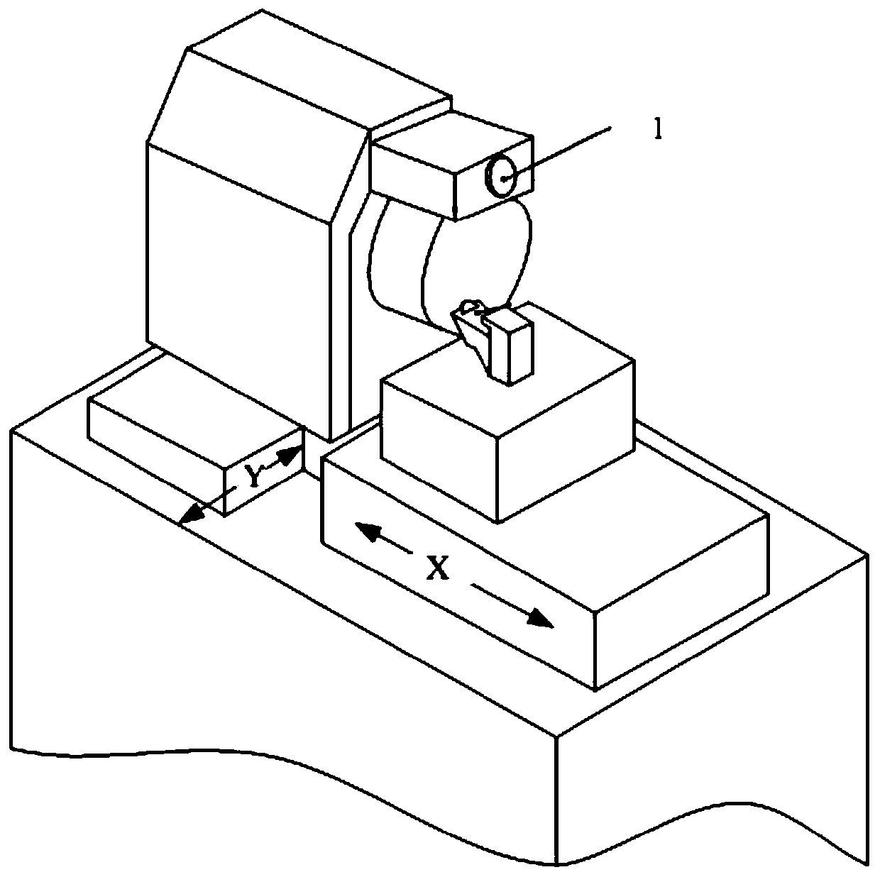
[0038] Such as figure 2 As shown, in this embodiment, the 3R high-precision pneumatic conversion fixture 1 is a pneumatic clamping method, the repeat positioning accuracy is 1 μm, and the effective load is 10 kg. The base of the 3R high-precision pneumatic conversion fixture 1 is assembled on the machine tool.

[0039] In this embodiment, the coaxial point light source 6 is a white light ...


PUM


Abstract

The invention discloses a detecting module and a detecting method for abrasion of a cutting edge of a diamond tool, and belongs to the technical field of ultra-precise processing and detecting. The module comprises a 3R high-precision pneumatic conversion clamp, an adapter plate, a microscope tube Z-direction motion table, a monocular zoom microscope tube, a coaxial point light source, a microscope objective, a CCD camera, a spectral confocal sensor, a spectral confocal controller, a spectral confocal sensor Z-direction motion table, an image acquisition card, a motion controller and a PC processor. A composite measuring means of micro-vision and spectral confocal measurement is adopted, and XY axes of a processing machine tool are utilized to perform quick scanning analysis on abrasion ofthe cutting edge of the diamond tool; relevance between abrasion depth of the cutting edge and image grey is utilized, and two-dimensional data of the image is restored to a two-dimensional diagram through an SFS method, and is subjected to data fusion with three-dimensional data of spectral confocal measurement, so that evaluation on abrasion of the cutting edge is realized. The detecting modulecan quickly integrate on an ultra-precise processing machine tool, and realizes greater-range three-dimensional abrasion detection of the tool surface.

Description

technical field [0001] The invention belongs to the technical field of ultra-precision machining and detection, and in particular relates to a diamond tool cutting edge wear detection module and a detection method. Background technique [0002] Due to its high hardness, good mechanical properties and thermal conductivity, diamond has good anti-bonding, corrosion and excellent chemical stability in the metal cutting process, and is currently the most ideal tool material for ultra-precision cutting. Because it can obtain a sharp cutting edge through micro-grinding, in metal ultra-precision machining, nano-level machining accuracy and surface roughness can be obtained. [0003] In the process of metal ultra-precision machining, the edge of the diamond tool is subjected to high mechanical pressure and cutting temperature, and the contact with the metal material during the cutting process dissolves, resulting in a decrease in the surface hardness and wear resistance of the diamon...

Claims


Application Information

Patent Timeline
Patent Type & Authority Applications(China)
IPC IPC(8): B23Q17/09B23Q17/24
Inventor 于占江于化东许金凯江海宇张向辉冯磊李成超
Owner CHANGCHUN UNIV OF SCI & TECH
Why Eureka
Try Eureka