A magnetoacoustic emission detection method for creep damage of ferromagnetic metal components

A technology for acoustic emission detection and metal components, which is applied in material analysis using acoustic emission technology, processing response signals of detection, and analysis of solids using acoustic/ultrasonic/infrasonic waves. Time and other problems, to achieve the effect of convenient extraction, increased signal-to-noise ratio, and easy identification

Active Publication Date: 2021-04-27
CHINA SPECIAL EQUIP INSPECTION & RES INST
View PDF11 Cites 0 Cited by
  • Summary
  • Abstract
  • Description
  • Claims
  • Application Information

AI Technical Summary

Problems solved by technology

(2) When Hmax is constant, as the frequency of the alternating magnetic field increases, the acoustic emission signal output by the material in unit time increases, and the MAE signal intensity gradually increases, but the adjacent signals overlap gradually. resulting in a decrease in the signal-to-noise ratio; it can be seen that increasing the strength and frequency of the alternating magnetic field can only improve the strength and signal ratio of the MAE signal to a certain extent
The acquisition of suitable conditions requires trial debugging of multiple parameters (such as magnetic field strength, magnetic field frequency, electromagnetic yoke core size and coil turns, nominal diameter of enameled wire, etc.), which is time-consuming and laborious, and requires on-site testing under working conditions. cause great inconvenience

Method used


Image

  • A magnetoacoustic emission detection method for creep damage of ferromagnetic metal components
  • A magnetoacoustic emission detection method for creep damage of ferromagnetic metal components
  • A magnetoacoustic emission detection method for creep damage of ferromagnetic metal components

Examples


Embodiment 1

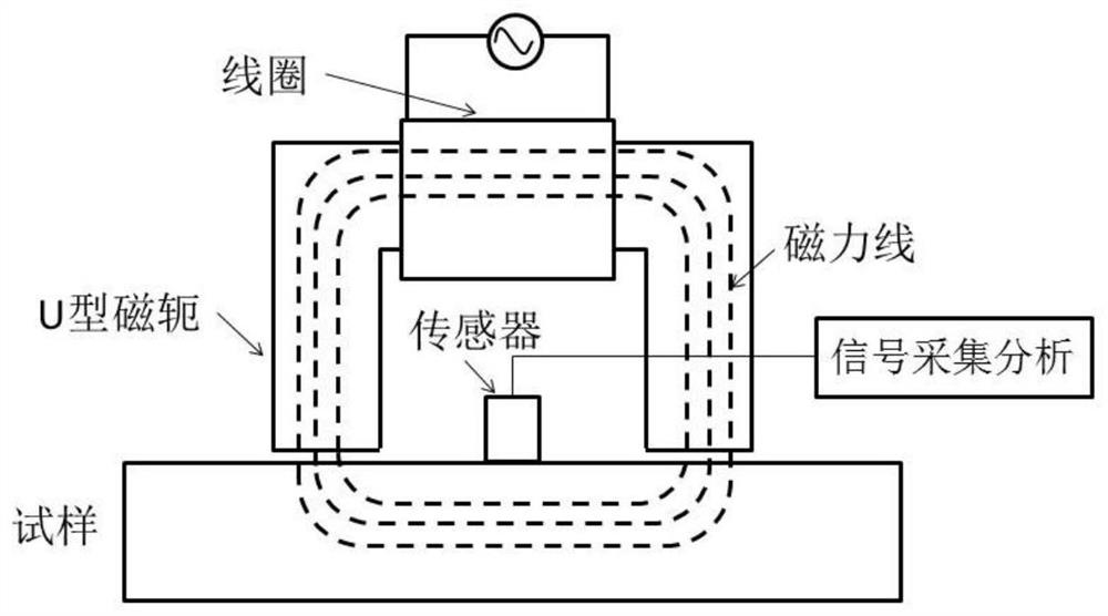
[0041] 1) Place the self-made U-shaped electromagnetic yoke and the acoustic emission sensor in the central area of ​​the 1Cr5Mo steel sample that has not been subjected to the creep test in a relatively fixed position.

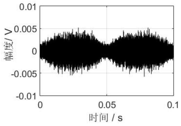
[0042] 2) Load a triangular wave voltage signal with a periodic symmetry of 50% to the coil of the U-shaped electromagnetic yoke. The frequency of the signal is 10 Hz. The voltage signal is generated by a function generator and input to the coil after being amplified 10 times by a power amplifier. Since the MAE signal is generated under the alternating magnetic field excited by the triangular wave voltage signal with a symmetry of 50%, the 1Cr5Mo steel sample generates two identical MAE signals within one magnetization period, that is, the frequency of the MAE signal is equal to the frequency of the alternating magnetic field double.

[0043] Use the function generator to increase the peak-to-peak value of the output voltage signal from 0.1Vpp with a gradient...

Embodiment 2

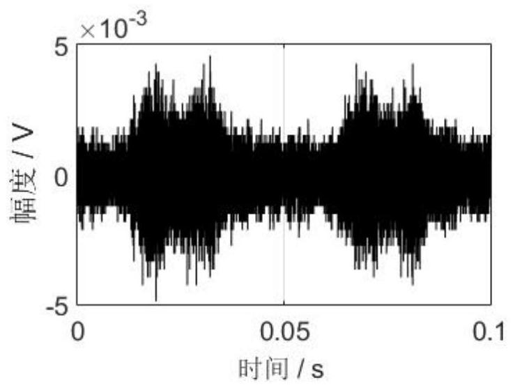
[0057] The same as the member to be tested and the detection steps described in Example 1, only the steps of adjusting the magnetomotive force are different, as follows:

[0058] By adjusting the nominal diameter of the coil enameled wire to obtain a "T"-shaped envelope, the number of turns of the U-shaped electromagnetic yoke coil is 800 turns, and the nominal diameter of the enameled wire for making the coil is 0.04mm, and the standard Enameled wires with diameters of 0.08mm, 0.12mm, 0.16mm, 0.2mm, 0.25mm, 0.31mm, 0.35mm, 0.4mm, 0.45mm, 0.5mm, 0.55mm, 0.60mm, 0.64mm, 0.69mm and 0.72mm are used instead Enameled wire with a nominal diameter of 0.04mm is wound on the core with a coil having the same number of turns. Keep the voltage signal unchanged, collect the MAE signal and the corresponding coil current under the coils wound by enameled wires with various nominal diameters, and find that the MAE signal of the "T"-shaped envelope is generated when the nominal diameter of the...


PUM


Abstract

A magnetoacoustic emission detection method for creep damage of ferromagnetic metal components. First, a triangular wave voltage signal with a symmetry of 50% is used to generate an excitation magnetic field, and the loading voltage is increased from small to large until a magnetic field with a shuttle-shaped envelope is obtained. The acoustic emission signal records the corresponding peak-to-peak voltage at this time; subsequently, a triangular wave signal with a symmetry of 0% or 100% is used to generate an excitation magnetic field with a voltage signal equal to or higher than the peak-to-peak voltage, by increasing the coil’s The magnetomotive force obtains the magnetoacoustic emission signal with a "T" shape envelope; again, calculates the peak voltage average value of the magnetoacoustic emission signal corresponding to the triangle wave voltage right-angle side in multiple cycles, and uses the average value as the detected value It is used to measure the characteristic parameters of stress state, creep or fatigue damage degree of ferromagnetic metal components.

Description

technical field [0001] The invention belongs to the technical field of nondestructive detection of material damage, and in particular relates to a magnetoacoustic emission detection method for creep damage of ferromagnetic metal components. Background technique [0002] Magneto acoustic emission (MAE for short) refers to the phenomenon of acoustic emission produced by ferromagnetic metal materials due to changes in the magnetic domain structure under the action of an alternating magnetic field. For the detection principle of MAE technology, please refer to the attached figure 1 : An alternating current or voltage is applied to both ends of the coil of the U-shaped electromagnetic yoke, and the coil generates an alternating magnetic field to repeatedly magnetize the ferromagnetic metal member that forms a magnetic circuit with the yoke. Due to the anisotropy of the magnetic crystal, the irreversibility of the magnetic domain wall Displacement, the generation and annihilation...

Claims


Application Information

Patent Timeline
Patent Type & Authority Patents(China)
IPC IPC(8): G01N29/04G01N29/14G01N29/44G01N29/46
Inventor 沈功田沈永娜高广兴张文君
Owner CHINA SPECIAL EQUIP INSPECTION & RES INST
Why Eureka
Try Eureka