Fuel battery and new energy automobile

A fuel cell and electric stack technology, which is applied in the direction of fuel cells, fuel cell additives, fuel cell heat exchange, etc., can solve the problems of poor integration installation flexibility and low efficiency of fuel cell systems, and achieve high assembly efficiency and small flow resistance , Good effect of installation and integration flexibility

Pending Publication Date: 2019-06-18
ZHONGSHAN BROAD OCEAN
View PDF4 Cites 13 Cited by
  • Summary
  • Abstract
  • Description
  • Claims
  • Application Information

AI Technical Summary

Problems solved by technology

[0005] The purpose of the present invention is to provide a fuel cell and a new energy vehicle, which solves the technical problems of low efficiency of the fuel cell system and poor flexibility of integration and installation in the prior art fuel cells composed of large-scale integration

Method used


Image

  • Fuel battery and new energy automobile
  • Fuel battery and new energy automobile
  • Fuel battery and new energy automobile

Examples


Embodiment 1

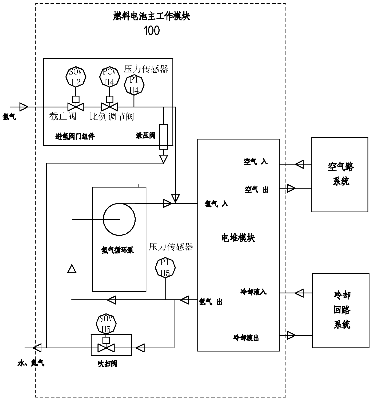
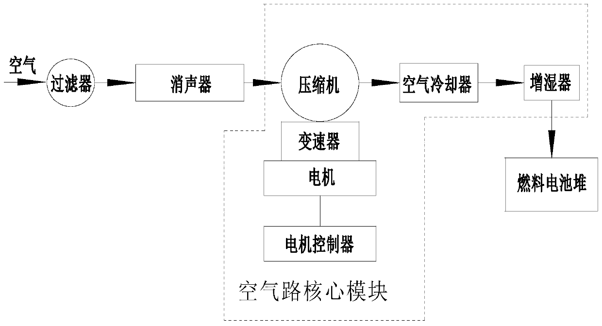
[0041] Such as figure 1 , figure 2 , image 3 As shown, the present invention provides a fuel cell, including a stack module, an electrical control assembly ( figure 1 , figure 2 , image 3 Not shown), hydrogen circuit system, cooling circuit system and air circuit system, the hydrogen circuit system includes a hydrogen inlet valve assembly, a hydrogen circulation pump and a purge valve; the stack module is composed of several fuel cell monomers Stacked from bottom to top, the cooling circuit system includes a water pump, a water pump controller, and a thermostat valve; the air circuit system includes an air compressor, an air cooler, and a humidifier; it is characterized in that: the electric stack module , electrical control components, and hydrogen circuit system are installed in a box to form the main working module of the fuel cell, and the stack module is connected to the hydrogen circuit system with pipelines; the air compressor, air cooler and humidifier are inte...

Embodiment 2

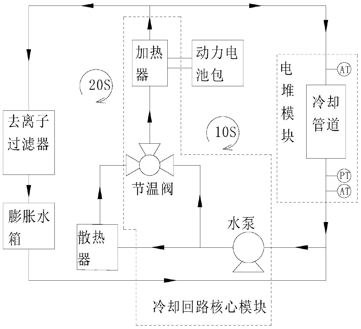
[0051] This embodiment provides a new energy vehicle, including a vehicle frame, a driving motor and a fuel cell. The fuel cell provides electric energy for the driving motor. The core module of the cooling circuit and the core module of the air circuit are independently installed in different positions of the vehicle frame. The main working module of the fuel cell is connected with the core module of the cooling circuit by pipelines, and the main working module of the fuel cell and the core module of the air circuit are connected by pipelines. connect them.

[0052] The above-mentioned cooling circuit system also includes a radiator, a deionization filter and an expansion tank. The radiator, the deionization filter and the expansion tank are located outside the core module of the cooling circuit and are installed on the vehicle frame. The radiator, deionization The filter and expansion tank draft lines are connected to the core module of the cooling circuit.

[0053] The abo...


PUM


Abstract

The invention discloses a fuel battery and a new energy automobile. The fuel battery comprises an electric pile module, an electrical control component, a hydrogen path system, a cooling loop system and an air path system, wherein the electric pile module, the electrical control component and the hydrogen path system are installed in one box body so as to form a main working module of the fuel battery, an air compressor, an air cooler and a humidifier are integrated in one first support so as to form an air path core module, a water pump, a water pump controller and a thermostat valve are integrated on a second support so as to form a cooling loop core module, the main working module of the fuel battery is separated from the cooling loop core module and the air path core module in space, and is connected with the cooling loop core module and the air path core module through pipelines, so that connecting pipelines of air and cooling liquid have small turning angles, the air path and thecooling liquid path have small flow resistance, power of the air compressor and water pump of the system is lowered, the efficiency is improved, and installation and integration are flexible.

Description

Technical field: [0001] The invention relates to a fuel cell and a new energy vehicle. Background technique: [0002] A fuel cell is a power generation device that can directly convert the chemical energy stored in the fuel into electrical energy through an electrochemical reaction. The device that performs the chemical reaction is often called a "stack" or "stack module". The cathode side is continuously supplied with fuel (generally hydrogen) and oxidant (generally air), and it can continuously output electric energy through oxidation-reduction reactions. Different from general rechargeable batteries (such as lithium batteries), a single fuel cell or fuel cell stack unit cannot work. It needs a complex auxiliary system to cooperate with it to form a fuel cell power generation system to generate electricity externally. . A typical fuel cell power generation system generally includes hydrogen supply in addition to the fuel cell stack. The proton exchange membrane fuel cell...

Claims


Application Information

Patent Timeline
Patent Type & Authority Applications(China)
IPC IPC(8): H01M8/04007H01M8/04029H01M8/04082H01M8/04089H01M8/04119
CPCY02E60/50
Inventor 李勇邓佳韦庆省王宏旭梁未栋易勇赵勇富刘静刘华李国坚张振涛毛锋锋
Owner ZHONGSHAN BROAD OCEAN
Why Eureka
Try Eureka