Two-stage thermoelectric material device

A technology of thermoelectric materials and thermoelectric elements, which is applied in the directions of thermoelectric device node lead-out materials, measuring devices, thermoelectric device components, etc., can solve the problems such as the inability to effectively utilize the figure of merit of thermoelectric materials and the low conversion efficiency of thermoelectric power generation devices, etc. To achieve the effect of improving power generation efficiency and improving safety

Active Publication Date: 2019-06-21
WUHAN UNIV OF TECH
View PDF6 Cites 2 Cited by
  • Summary
  • Abstract
  • Description
  • Claims
  • Application Information

AI Technical Summary

Problems solved by technology

[0003] Existing thermoelectric material devices are usually composed of a single P-shaped component and an N-shaped component arranged in an interlaced manner, which cannot effectively utilize the figure of merit of thermoelectric materials, thus resulting in low conversion efficiency of thermoelectric power generation devices

Method used


Image

  • Two-stage thermoelectric material device
  • Two-stage thermoelectric material device
  • Two-stage thermoelectric material device

Examples


Embodiment 1

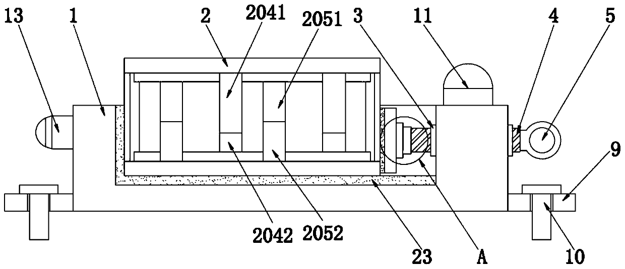
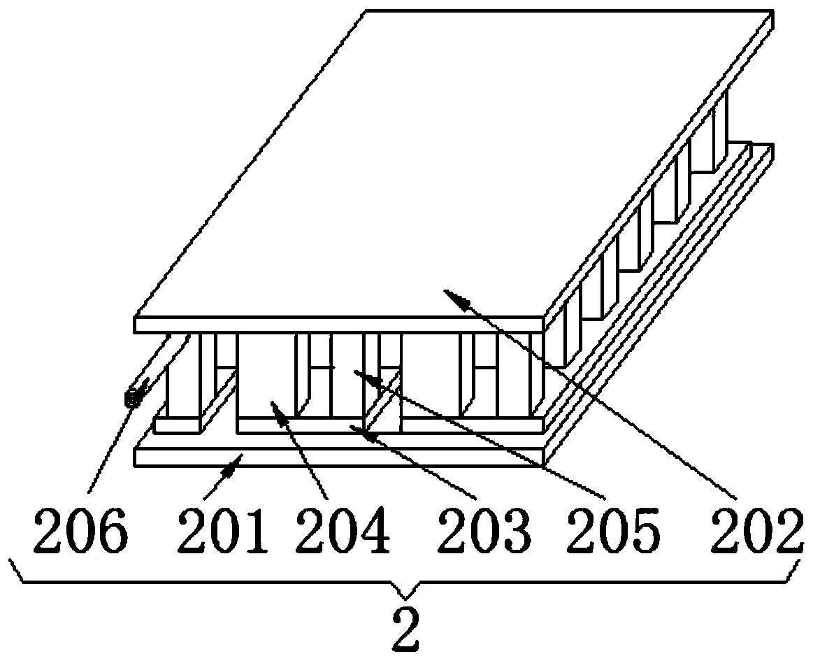
[0037] Embodiment 1 is the basic structure of a kind of embodiment, as figure 1 and figure 2As shown, it includes a base 1 and a thermoelectric device body 2, a groove is opened on the upper surface of the base 1, and a thermoelectric device body 2 is arranged inside the groove, and the thermoelectric device body 2 includes a lower substrate 201 and an upper substrate 202. , conductive plate 203, double-stage P-type thermoelectric element 204, double-stage N-type thermoelectric element 205 and electrode rod 206, the lower substrate 201 and the upper substrate 202 are symmetrically arranged, the lower surface of the lower substrate 201 and the groove The inner side wall is attached, and the opposite side of the lower substrate 201 and the upper substrate 202 are fixedly connected with a conductive plate 203, and the two-stage P-type thermoelectric element 204 and the double-stage N-type thermoelectric element are arranged alternately between the two conductive plates 203. ele...

Embodiment 2

[0047] Embodiment 2 is a technical solution further optimized on the basis of Embodiment 1. On the basis of Embodiment 1, Embodiment 2 further adds a fixing device arranged between the base 1 and the thermoelectric device body 2 .

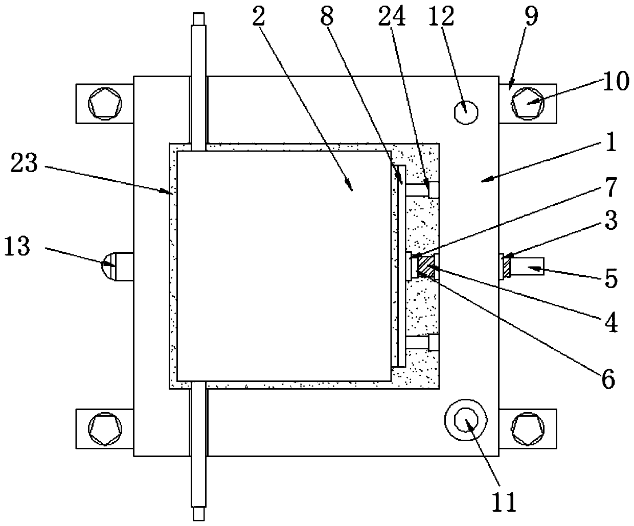
[0048] Such as figure 1 , image 3 and Figure 7 As shown, the fixing device includes a threaded cap 3 clamped on the side of the base 1, and the threaded cap 3 is internally threaded with a threaded column 4, and the threaded column 4 passes through one end of the base 1 and is fixed to the rotating handle 5;

[0049] The left end of the threaded column 4 is fixedly connected to the right end of the rotating shaft 6, the outer surface of the rotating shaft 6 is sleeved with a bearing 7, and the bearing 7 is clamped on the right side of the extruding plate 8, and the extruding plate 8 The left side of the base 1 is attached to the right side of the thermoelectric device body 2, and two mounting plates 9 are respectively fixed under the left and r...

Embodiment 3

[0057] Embodiment 3 is a technical solution further optimized on the basis of Embodiment 1 or Embodiment 2, and Embodiment 3 further adds a temperature control device arranged on the base on the basis of Embodiment 1 or Embodiment 2.

[0058] Such as Figure 4 and Figure 5 As shown, the temperature control device includes an alarm horn 11 and an alarm lamp 12 fixedly installed on the upper surface of the base 1, a temperature sensor 13 is fixedly installed on the left side of the base 1, and a control box 14 is arranged on the front. The front of box 14 is fixedly installed with display screen 15 and control button, and described control box 14 is provided with single-chip microcomputer 17 and battery slot;

[0059] The single-chip microcomputer 17 is provided with a signal conversion module 18, a storage module 19, a comparison module 20 and an alarm module 21, the input of the signal conversion module 18 and the output signal of the temperature sensor 13, the output of the...


PUM


Abstract

The invention discloses a two-stage thermoelectric material device comprising a base and a thermoelectric device body, wherein the upper surface of the base is provided with a groove, the thermoelectric device body is disposed inside the groove and comprises a lower substrate, an upper substrate, a conductive plate, a two-stage P-type thermoelectric element, a two-stage N-type thermoelectric element and an electrode rod, and the lower substrate is symmetrically arranged with the upper substrate. By providing a threaded column, a rotating shaft, a bearing, a pressing plate, a mounting plate anda bolt, when the thermoelectric device body is mounted and fixed, the rotation of a rotary handle drives the rotation of the threaded column to drive the rotating shaft to rotate in the bearing suchthat the pressing plate moves to the left to fix the thermoelectric device body in the groove; at the same time, a telescopic rod can be used to limit the pressing plate to improve the security assurance; by using the two-stage P-type thermoelectric element and the N-type thermoelectric element to superimpose and use the thermoelectric materials of different temperature domains in parallel, physical property characteristics of different materials can be fully utilized, so as to effectively improve the power generation efficiency of the thermoelectric device.

Description

technical field [0001] The invention relates to the technical field of thermoelectric materials, in particular to a double-stage thermoelectric material device. Background technique [0002] A unit that can independently control and transform electronic and electrical instruments is often composed of several components, and sometimes refers to larger components. Thermoelectric materials are functional materials that can convert heat energy and electrical energy. Thermoelectric material devices are used Assemblies of components made of thermoelectric materials, with the increasing interest in space exploration, the progress of medical physics, and the increasingly difficult resource exploration and exploration activities on the earth, it is necessary to develop a type of power system that can supply energy by itself and does not need to be looked after. Thermoelectric power generation is especially suitable for these applications. Both natural temperature difference and indus...

Claims


Application Information

Patent Timeline
Patent Type & Authority Applications(China)
IPC IPC(8): H01L35/02H01L35/14H01L35/16H01L35/18G01K1/02
Inventor 肖金生李想陈哲航马硕杨天麒
Owner WUHAN UNIV OF TECH
Why Eureka
Try Eureka