Step-down circuit

A technology of step-down circuit and charging and discharging circuit, applied in the field of circuits, can solve the problems of high manufacturing cost, difficult realization and low efficiency of switching power supply, and achieve the effect of small product size, low cost and high efficiency

Inactive Publication Date: 2019-06-21
MORNSUN GUANGZHOU SCI & TECH
View PDF0 Cites 6 Cited by
  • Summary
  • Abstract
  • Description
  • Claims
  • Application Information

AI Technical Summary

Problems solved by technology

[0002] In the existing power supply technology, linear regulators or switching power supplies are generally used for DC voltage step-down. Linear regulators are only suitable for low-voltage and low-power occasions, and the efficiency is extremely low; and switching power supply step-down technology, although it has high working efficiency , to adapt to the functional characteristics such as wide voltage range, but the manufacturing cost of switching power supply is relatively expensive, and it is difficult to realize the application occasions that need to step down and have strict requirements on its efficiency and cost control.

Method used


Image

  • Step-down circuit
  • Step-down circuit
  • Step-down circuit

Examples


specific Embodiment 1

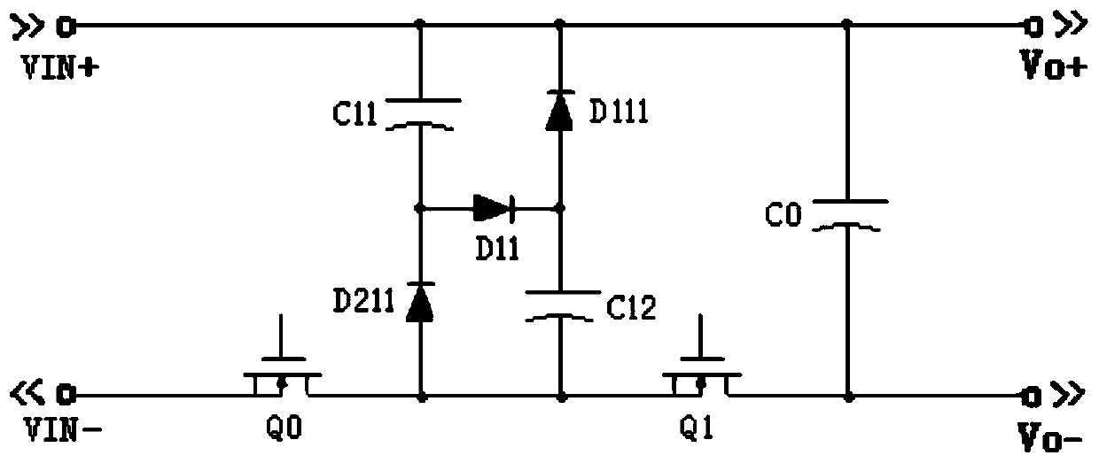
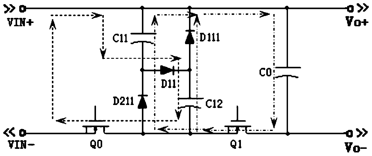
[0051] Figure 1-a Shown is the schematic circuit diagram of the specific embodiment 1 of the present invention, Figure 1-b The schematic diagram of the circuit loop formed when the circuit of this embodiment is working, the step-down circuit of this embodiment includes: a two-stage charging and discharging circuit: capacitor C11, capacitor C12, diode D211, diode D11, diode D111, two switch tubes: switch tube Q0 , switch tube Q1, output capacitor C0, input positive pole VIN+, input negative pole VIN-, output positive pole Vo+, output negative pole Vo-; the connection relationship is: the input positive pole VIN+ passes through the first and second ends of capacitor C11 and the cathode of diode D211 in turn And the anode, the current inflow terminal and the current outflow terminal of the switch tube Q0 are connected to the input negative pole VIN-, and the input positive pole VIN+ is also sequentially passed through the cathode and anode of the diode D111, the first terminal a...

specific Embodiment 2

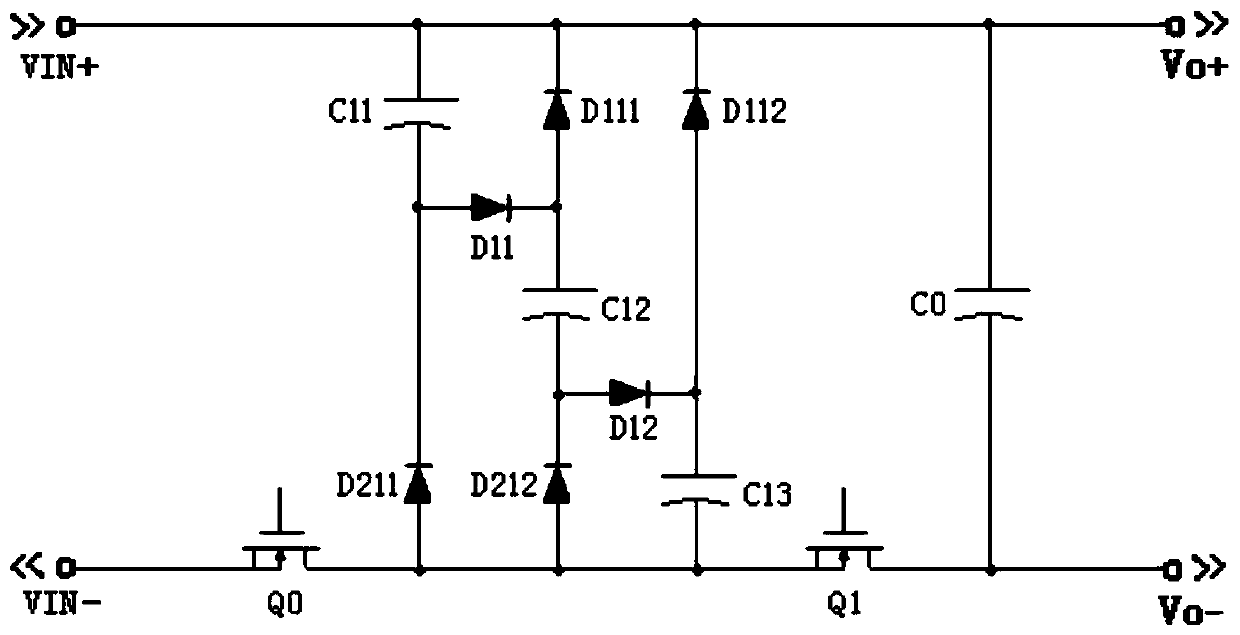
[0055] Figure 2-a Shown is the circuit schematic diagram of Embodiment 2 of the present invention, Figure 2-b A schematic diagram of the circuit forming a loop when the circuit of this embodiment works, and Figure 1-a The difference is that the step-down circuit of this embodiment includes a three-stage charging and discharging circuit, switching tubes Q0 and Q1, and an output capacitor CO. The working principle of the charging and discharging circuit of this embodiment is the same as that of the first embodiment.

[0056] In this embodiment, the driving waveforms of the switching tubes Q0 and Q1 are as follows Figure 4 As shown, the switching tube Q0 and the switching tube Q1 work alternately. When the switching tube Q0 is turned on and the switching tube Q1 is turned off, Figure 2-b The loop formed by the circuit: the input voltage sequentially passes through the capacitor C11, diode D11, capacitor C12, diode D12, capacitor C13, and switch tube Q0 to form a series char...

specific Embodiment 3

[0058] Figure 3-a Shown is the schematic circuit diagram of Embodiment 3 of the present invention, Figure 3-b A schematic diagram of the circuit forming a loop when the circuit of this embodiment works, and Figure 1-a The difference is that this embodiment expands the circuit to include N-level charging and discharging circuits, where N is a natural number ≥ 2. The working principle of the adjusted circuit is the same as that of Embodiment 1. The driving control of the switching tubes Q0 and Q1 in this embodiment is as follows: As shown in Figure 4, the switching tube Q0 and the switching tube Q1 are turned on alternately, when the switching tube Q0 is turned on and the switching tube Q1 is turned off, Figure 3-b The loop formed by the middle circuit: the input voltage forms a series charging circuit through capacitor C11, diode D11, capacitor C12, diode D12,..., diode D1N-1, capacitor C1N, and switch tube Q0, and charges and stores N capacitors Energy, the voltage of N c...


PUM


Abstract

The invention provides a step-down circuit, comprising N stages of charging and discharging circuits, two stages of switching tubes, an output capacitor C0, an input positive pole VIN+, an input negative pole VIN-, an output positive pole Vo+, an output negative pole Vo-, and N is a natural number more than or equal to 2; the N stages of charging and discharging circuits are used for enabling an input voltage to be subjected to 1 / N step-down; the switching tubes alternately work, so that the N stages of charging and discharging circuits perform series charging when a first-stage switching tubeis on and a second-stage switching tube is off and perform N-stage parallel discharging when the first-stage switching tube is off and the second-stage switching tube is on, and the output capacitoris charged, so that the 1 / N step-down of the input voltage is realized; meanwhile, circuit structure is simple, step-down can be realized without using a high-power transformer, the efficiency is high, and the size is small.

Description

technical field [0001] The invention relates to a circuit, in particular to a step-down circuit. Background technique [0002] In the existing power supply technology, linear regulators or switching power supplies are generally used for DC voltage step-down. Linear regulators are only suitable for low-voltage and low-power occasions, and the efficiency is extremely low; and switching power supply step-down technology, although it has high working efficiency , to adapt to functional characteristics such as wide voltage range, but the manufacturing cost of switching power supply is relatively expensive, and it is difficult to realize the application occasions that need to step down and have strict requirements on its efficiency and cost control. [0003] Therefore, it is necessary to improve the prior art. Contents of the invention [0004] In view of this, the technical problem to be solved by the present invention is to provide a step-down circuit with few components, hig...

Claims


Application Information

Patent Timeline
Patent Type & Authority Applications(China)
IPC IPC(8): H02M3/07
Inventor 申志鹏翁斌王小亮
Owner MORNSUN GUANGZHOU SCI & TECH
Why Eureka
Try Eureka