Self-driven microfluidic chip and method for using same

A microfluidic chip, self-driven technology, applied in fluid controllers, chemical instruments and methods, biochemical equipment and methods, etc., can solve the problems of complex chip operation, achieve low experimental cost, avoid pollution, and prevent fusion effects. Good results

Active Publication Date: 2019-06-25
SHENZHEN SHINEWAY HI TECH CO LTD
View PDF5 Cites 16 Cited by
  • Summary
  • Abstract
  • Description
  • Claims
  • Application Information

AI Technical Summary

Problems solved by technology

In the related manipulation of microfluidic chips, equipment such as syringes or air pumps and electric pumps are usually used to drive rea

Method used


Image

  • Self-driven microfluidic chip and method for using same
  • Self-driven microfluidic chip and method for using same
  • Self-driven microfluidic chip and method for using same

Examples


Embodiment 1

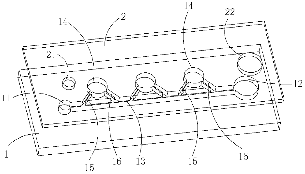
[0036] This implementation relates to a self-driven microfluidic chip, which is used to accommodate the sample solution to be tested, so as to perform various detection operations such as real-time fluorescent quantitative PCR detection or digital PCR detection on the sample solution to be tested. Such as figure 1 As shown in , the self-driven microfluidic chip includes a substrate 1 and an encapsulation sheet 2, at least one of the substrate 1 and the encapsulation sheet 2 is a colorless and transparent material, and the colorless and transparent material should also be self-low fluorescent , and the low fluorescence characteristic of this embodiment is generally that under the irradiation of the excitation light wavelength of the fluorescent probes used in PCR reagents such as FAM, HEX, VIC, CY3, TAMRA, ROX, CY5, etc., the excited fluorescence intensity of the material is less than 10e Fluorescence intensity of -8mol / L fluorescein. Due to the low fluorescence characteristic...

Embodiment 2

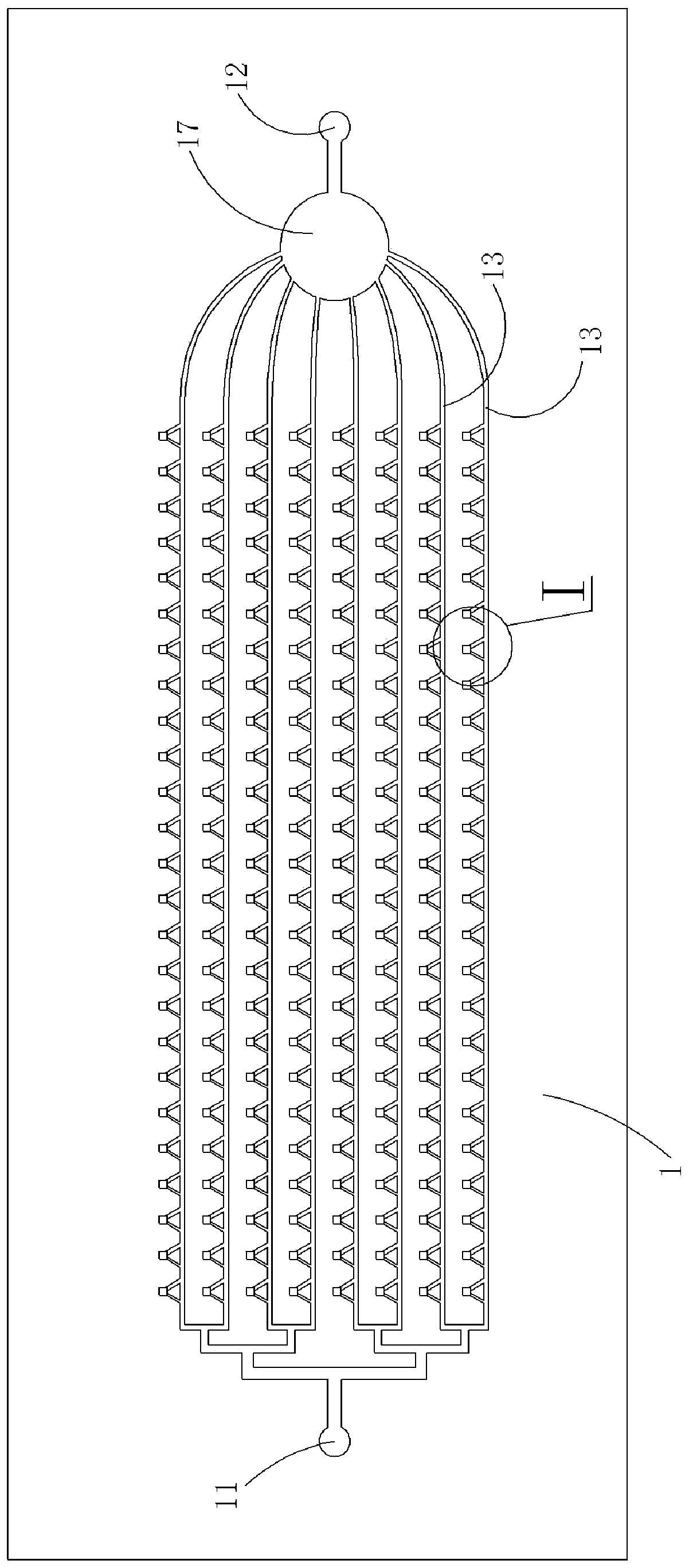
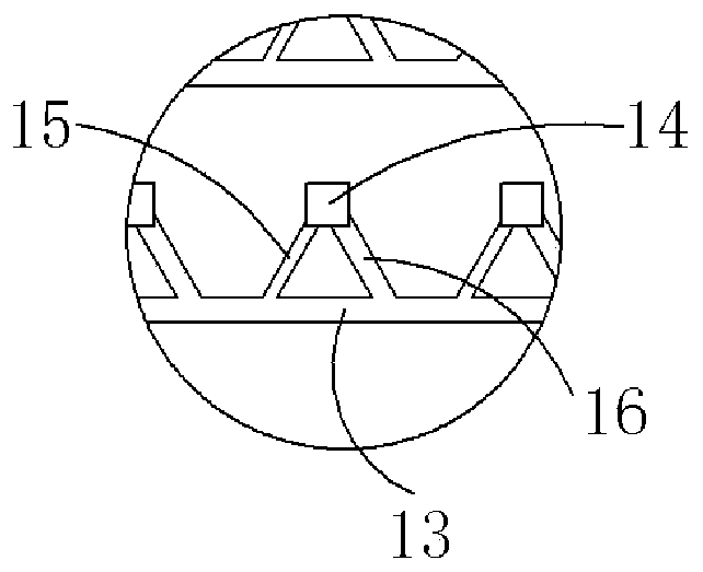
[0056] This implementation involves a self-driven microfluidic chip, which has roughly the same structure as the self-driven microfluidic chip in Example 1, the difference lies in the combination figure 2 and image 3 As shown in , in this embodiment, there are multiple main channels 13, and a waste liquid pool 17 is provided between these main channels 13 and the sample outlet 12, and the structure of the reaction chamber 14 is square. The solution to be tested or the oil phase reagent in each main channel 13 can enter the waste liquid pool 17 and then flow to the sample outlet 12 .

[0057] In addition, when the self-driven microfluidic chip of this embodiment is used for real-time fluorescent quantitative PCR detection or digital PCR nucleic acid detection, its specific method of use includes the following steps, and the sample solution to be tested hereinafter can be commercialized HBV DNA fragments. When the self-driven microfluidic chip of the first embodiment is used...


PUM


Abstract

The invention provides a self-driven microfluidic chip and a method for using the same. The self-driven microfluidic chip includes a substrate and a packaging sheet. A sample inlet, a sample outlet, aplurality of reaction chambers and one or more main channels are formed between the substrate and the packaging sheet. The sample inlet and the sample outlet can be communicated with the outside, themain channels are communicated with the sample inlet and the sample outlet, and liquid inlet channels and a liquid outlet channel are disposed between each of the reaction chambers and one main channel. The inner surfaces of the main channel, the reaction chambers, the liquid inlet channels and the liquid outlet channel located on the substrate and/or the packaging sheet are hydrophilic surfaces,the cross sectional area of the liquid inlet channel is smaller than that of the liquid outlet channel, and in the liquid flow direction in the main channel, the liquid inlet channels are located onthe front side of the liquid outlet channel. After a to-be-tested sample solution enters the reaction chamber, an oil phase reagent can be led into the main channel to seal the liquid inlet channels and the liquid outlet channel. The self-driven microfluidic chip can achieve self-driven flowing sample loading of the to-be-tested sample solution without an external driving device.

Description

technical field [0001] The invention relates to the field of microfluidic chips, in particular to a self-driven microfluidic chip and a method for using the same. Background technique [0002] In the past 20 years, there have been more than 2.2 million new cancer cases in my country every year. At the same time, the new cases are still increasing at a rate of 3%-5% every year. Cancer has become the number one cause of death affecting the life and health of our people. The occurrence of cancer needs to go through several steps such as gene mutation, cancer cell generation, tumor formation and finally metastasis and spread. The current methods of cancer diagnosis mainly include pathological examination and imaging examination. More accurate detection results cannot be obtained until the tumor grows to a certain size and the cancer develops in the middle and late stages, which often misses the best treatment time for patients. If the detection of mutated genes can be realized ...

Claims


Application Information

Patent Timeline
IPC IPC(8): C12M1/34C12M1/00C12Q1/6851
CPCB01L3/502769B01L7/52B01L2200/0689B01L2300/0636B01L2300/0816B01L2300/0864B01L2400/0406B01L2200/142B01L2300/087B01L2200/0621
Inventor 温维佳高一博宋祺
Owner SHENZHEN SHINEWAY HI TECH CO LTD
Why Eureka
Try Eureka