Automatic die carrying die change system and method in unmanned state

A mold, automatic technology, used in motor vehicles, transportation and packaging, etc., can solve problems such as unreasonable structure, lack of elevators, high synchronization and resistance to lateral forces, and achieve the effect of improving stability

Pending Publication Date: 2019-06-28
QINGDAO LICI ELECTRIC
View PDF4 Cites 19 Cited by
  • Summary
  • Abstract
  • Description
  • Claims
  • Application Information

AI Technical Summary

Problems solved by technology

[0013] The above process is estimated to take about 3 hours. The processing time is long, the labor cost is high, the production efficiency is low, the labor intensity is high, and the utilization rate of the injection molding machine is low.
[0014] Moreover, the traditional heavy-duty mold warehouse can only be stacked in one layer, and it is docked with the mold changing vehicle, while the heavy-duty mold is generally very large in shape and occupies a large area. The mold library is used to accommodate it, resulting in a large footprint and wasting unnecessary space
[0015] In addition, the elevating mold changing vehicle for heavy molds usually uses a heavy-duty screw elevator, and the way of inversion is used to meet the minimum table height and maximum lifting range, because the elevating mold changing vehicle generally only works when it is lifting. Carrying the mold on one station table will cause uneven load on the whole table, so the elevator does not have high synchronization and lateral force resistance
[0016] After retrieval, CN108861399 discloses a non-contact power supply intelligent heavy-duty mold transfer vehicle, a method for transporting and changing molds. When transporting and changing molds, two transfer vehicles are required. When the first transfer vehicle hooks the new mold through its push-pull mechanism Mold, pull it on the first transfer vehicle, then the first vehicle follows the second empty t...

Method used


Image

  • Automatic die carrying die change system and method in unmanned state
  • Automatic die carrying die change system and method in unmanned state
  • Automatic die carrying die change system and method in unmanned state

Examples


Embodiment Construction

[0073] Below in conjunction with accompanying drawing, the present invention is further described:

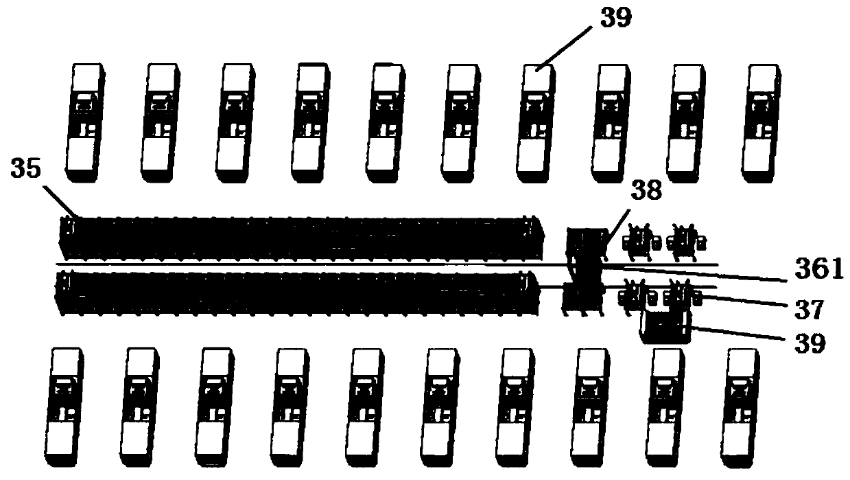
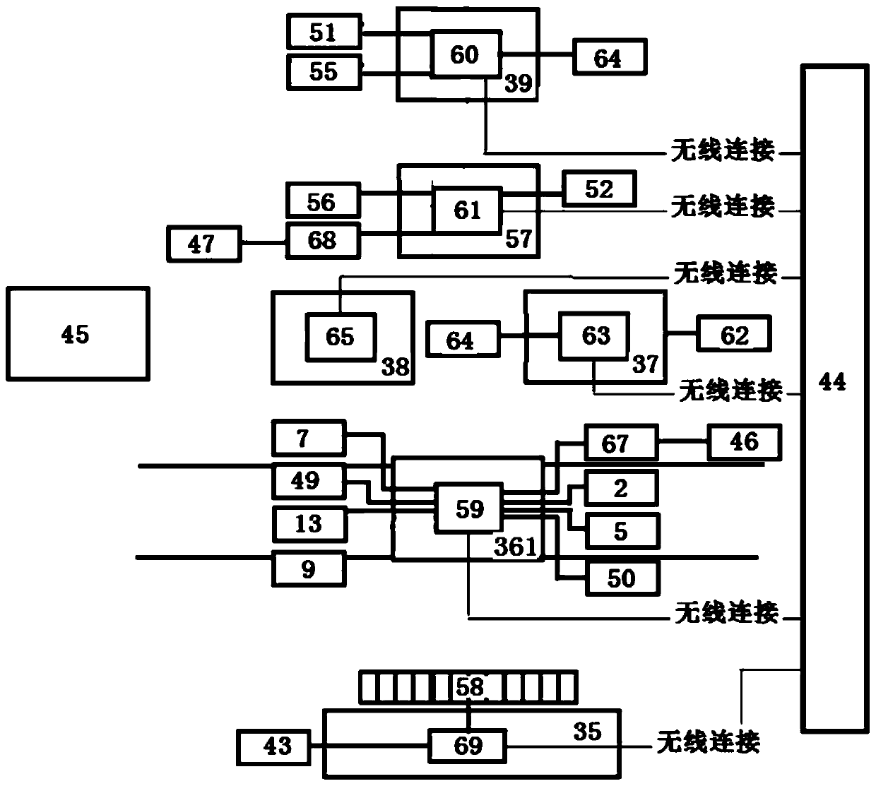
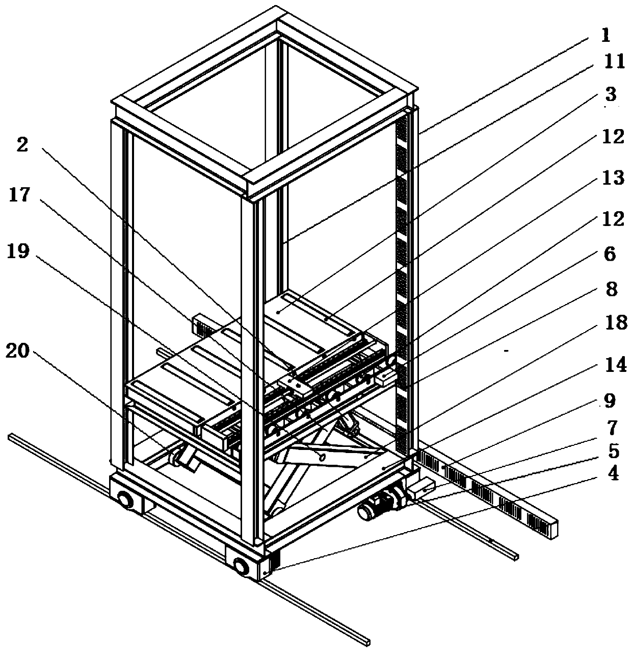
[0074] As shown in the accompanying drawings, an automatic mold transfer and mold change system in an unmanned state includes a mold library 35, a mold transport vehicle 361, a preheating station 37, a transition platform 38, a mold change trolley 57, an injection molding machine 39 and a control system. System 44 is characterized in that it also includes automatic charging station 45, first charging module 46, second charging module 47, RFID electronic tag 48, RFID card reader 49, wireless communication module 50, two-dimensional code 51, two-dimensional code identification Device 52, walking positioning code reader 53, unit position sensor 54, first wireless communication module 55, second wireless communication module 56, walking positioning code reading device 7, walking barcode 9, transition platform mold in-position switch 65, control chip 59 , transition platform control...


PUM


Abstract

The invention discloses an automatic die carrying die change system in an unmanned state. The system comprises a die library, a die carrying vehicle, a preheating station, a transition platform, an injection molding machine and a control system. The system is characterized by further comprising an automatic charging station, a first charging module, a second charging module, RFID electronic tags,an RFID card reader, a wireless communication module, a two-dimensional code, a two-dimensional code recognizer, a walking positioning code reader, a unit position sensor, a first wireless communication module and a second wireless communication module. Due to the adoption of the structure, the automatic die change process only lasts for 3 min, the die change time is remarkably shortened, the production efficiency is improved, the labor cost is greatly reduced, and the system has the beneficial effects that the automation degree is high, the production efficiency is high, the labor cost is low, the occupied space is small, the use rate of the injection molding machine is high, and lifting is stable.

Description

technical field [0001] The invention relates to the technical field of mold processing equipment, in particular to a system and method for automatic mold transfer and mold change under unmanned conditions. Background technique [0002] At present, the processing of existing molds usually manually transports the mold from the mold warehouse to the trolley, and then manually operates the trolley to transport the mold to the preheating station, manually transports the mold to the preheating station for preheating, and then operates the trolley to transport the mold To change the mold on the injection molding machine, the mold change process is as follows: [0003] 1) After the injection molding machine is produced, manually operate the injection molding machine to clamp the mold (the mold that has been produced); [0004] 2) Open the safety door, manually disconnect the water circuit, hydraulic oil circuit, circuit and other signal connections between the injection molding mac...

Claims


Application Information

Patent Timeline
IPC IPC(8): B29C45/17B29C45/76B62D61/10
Inventor 李川郭强孙鹏王令军
Owner QINGDAO LICI ELECTRIC
Why Eureka
Try Eureka