Supercharge Your Innovation With Domain-Expert AI Agents!

Small-sized microwave oven with precession rotating disc

A microwave heating furnace and turntable technology, applied in the field of microwave ovens, can solve problems such as complex measurement, difficult calculation, and excessive complexity of microwave heating problems

Inactive Publication Date: 2019-06-28
成都赛纳为特科技有限公司
View PDF3 Cites 0 Cited by
  • Summary
  • Abstract
  • Description
  • Claims
  • Application Information

AI Technical Summary

Problems solved by technology

At the frequency of the working microwave, for a microwave feeder, after selecting its position, shape, and polarization direction, it is very difficult to determine the excitation intensity of several to dozens of modes in the heating cavity. , it is also extremely complicated in actual measurement
However, a large microwave oven needs to use multiple magnetrons as microwave sources, so the number of corresponding microwave feeders is also multiple, and the complexity of microwave oven heating is beyond people's imagination.

Method used


Image

  • Small-sized microwave oven with precession rotating disc
  • Small-sized microwave oven with precession rotating disc
  • Small-sized microwave oven with precession rotating disc

Examples


Embodiment 1

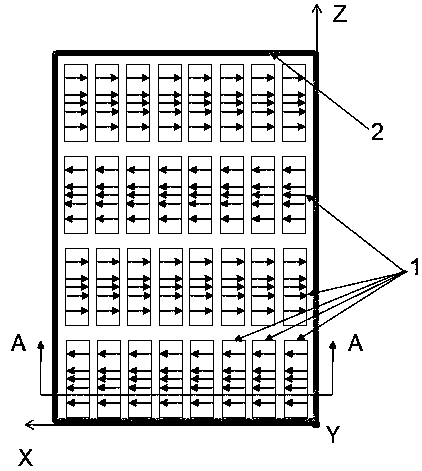
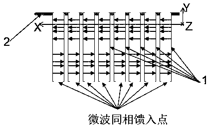
[0079] Such as figure 1 and 2 .

[0080] A radiation array includes 4 rows of radiators 1 along the Z axis and 8 columns of radiators 1 along the X axis. The radiation array radiates microwave energy to the heating cavity through the floor 2 .

[0081] The radiators 1 on the radiation array are evenly distributed along the X direction and along the Z direction. At the same time, the microwaves radiated by all radiators 1 on the radiation array are coherent waves. The microwaves radiated by all the radiators 1 arranged in the same row along the X-axis on the radiation array have the same amplitude and the same phase. The microwaves radiated by any two adjacent radiators 1 belonging to the same row on the same radiation array along the Z axis have the same amplitude and opposite phases.

[0082] The microwaves radiated by all the radiators 1 on the radiation array point to the X direction in the direction of the electric field on the center line of each radiator 1 along one...

Embodiment 2

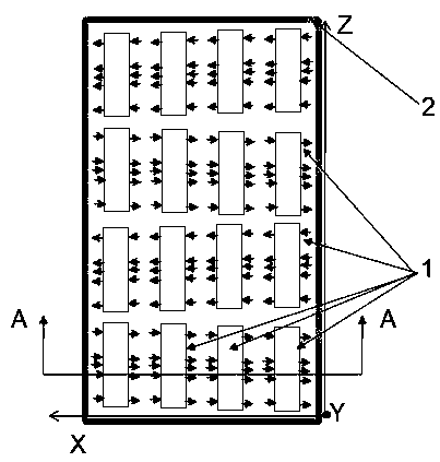
[0086] Such as image 3 with 4 shown.

[0087] Compared with Embodiment 1, the only difference is that the radiator 1 is a patch antenna. The antenna mainly includes a metal sheet radiator on the surface of the dielectric material sheet supported by a dielectric material sheet and a microwave excitation structure on the other surface of the dielectric material sheet opposite to the metal sheet radiator. The distance between the centers of adjacent patch antennas along the Z axis is 3 / 5-9 / 10 of the wavelength of the working microwave free space. The distance between the centers of adjacent patch antennas along the X axis is less than half of the wavelength of the working microwave free space. The patch antenna is rectangular.

[0088] Different from the rectangular waveguide propagating the TE10 mode in Example 1, the patch antenna here radiates microwave energy through its two long sides perpendicular to the X axis.

Embodiment 3

[0090] Such as Figure 5 with 6 shown.

[0091] Compared with Embodiment 1, the only difference is that the radiator 1 is a coaxial antenna. The coaxial antenna here uses a coaxial line to feed microwave energy. The outer conductor of the coaxial line and the medium between the outer conductor and the inner conductor are cut off, but its inner conductor protrudes into free space. A metal disc is attached to the top of the inner conductor.

[0092] The distance between the centers of the adjacent coaxial antennas adjacent along the X axis and adjacent along the Z axis is 3 / 5~9 / 10 of the wavelength of the working microwave free space. The component of the electric field in the X-axis direction of the microwaves radiated by the radiators 1 arranged in the same column along the Z-axis on the center line of each radiator 1 along the X-axis is zero. The microwaves radiated by the radiators 1 arranged in the same row along the X axis on the same radiation array have a zero compo...


PUM


Abstract

The invention discloses a small-sized microwave oven with a precession rotating disc. The small-sized microwave oven with the precession rotating disc adopts one to two radiation arrays to be arrangedbehind or above a heating cavity of the small-sized microwave oven with the precession rotating disc to stimulate a higher-order-mode TEn0 mode (n is an integer, and is greater than or equal to 2) asmuch as possible so as to form standing waves in the heating cavity. The small-sized microwave oven comprises the heating cavity, at least one radiation array and the rotating disc located at the bottom of the heating cavity, the at least one radiation array each comprises at least two rows of radiators along the Z axis, and the radiation arrays radiate microwave energy to the heating cavity through a floor, the rotating disc rotates along the central axis in the perpendicular direction and proceed around the central line in the perpendicular direction of the heating cavity simultaneously. Compared with multiple resonance modes under which in a traditional microwave oven, microwave sources simultaneously stimulate respective energy in the heating cavity through waveguide and coupling holes so that control is difficult, the field distribution of the working mode of the small-sized microwave oven is determined and can be controlled; in order to further improve the heating uniformity, inventors use the rotating disc which can transversely and horizontally move or can proceed around the perpendicular axis of the heating cavity; according to the small-sized microwave oven with the precession rotating disc, the heating uniformity of the small-sized microwave oven with the precession rotating disc in a three-dimensional space is improved by controlling the microwave mode in a hollowcavity of the small-sized microwave oven with the precession rotating disc; and the small-sized microwave oven can be used for heating various materials or accelerating the speed of chemical reaction.

Description

technical field [0001] The present invention relates to microwave ovens. Specifically, it relates to a microwave oven for heating materials uniformly and efficiently using a high-order mode. Background technique [0002] Microwave energy can be used in place of various conventional heating methods. Microwave ovens use microwave energy to heat various foods and materials, and in the field of microwave chemistry, microwave energy is used to speed up various chemical reactions. Microwave energy is also used in the production of various materials such as nanomaterials and synthetic diamonds. [0003] In the traditional heating process, heat is conducted from the outside to the inside of the heated object, which belongs to surface heating, resulting in uneven temperature inside and outside the heated object. In microwave energy heating, microwaves are heated by the action of an electric field, causing the damped vibration of polar molecules to generate heat, which belongs to b...

Claims


Application Information

Patent Timeline
IPC IPC(8): F24C7/02F24C7/06H05B6/64H05B6/72H05B6/78
Inventor 王清源
Owner 成都赛纳为特科技有限公司
Features
  • R&D
  • Intellectual Property
  • Life Sciences
  • Materials
  • Tech Scout
  • Unparalleled Data Quality
  • Higher Quality Content
  • 60% Fewer Hallucinations
Learn More