Bilaterally-excited tangential magnetic steel hybrid excited brushless motor

A hybrid excitation and brushless motor technology, applied to synchronous motors with stationary armature and rotating magnets, magnetic circuit rotating parts, magnetic circuit shape/style/structure, etc., can solve the limitation of magnetic modulation efficiency and power density , low space utilization, low power density, serious geometric constraints of the stator, etc., to achieve the effect of high excitation efficiency, simple structure, simple and reliable brushless AC excitation

Active Publication Date: 2019-06-28
NANJING UNIV OF AERONAUTICS & ASTRONAUTICS
View PDF5 Cites 11 Cited by
  • Summary
  • Abstract
  • Description
  • Claims
  • Application Information

AI Technical Summary

Problems solved by technology

[0005] (1) The electric excitation circuit is constructed with the help of additional magnetic circuits and magnetic conductive components; this excitation method has a complex structure, and the magnetic modulation efficiency and power density are limited
[0006] (2) A special exciter and a rotating rectifier are used to realize two-stage brushless excitation; this excitation method has a complex structure and low reliability
[0007] (3) The stator electric excitation motor and the rotor permanent magnet motor are combined in parallel; the structure of this excitation method is still too complicated, and the space utilization rate and power density are low
[0008] In addition, the stator permanent magnet hybrid excitation motor sets the DC excitation winding on the stator, and the brushless excitation is simple and reliable; furthermore, the rotor of this type of motor is passive, which leads to serious geometric constraints on the stator, low utilization of motor materials and low excitation efficiency

Method used


Image

  • Bilaterally-excited tangential magnetic steel hybrid excited brushless motor
  • Bilaterally-excited tangential magnetic steel hybrid excited brushless motor
  • Bilaterally-excited tangential magnetic steel hybrid excited brushless motor

Examples


Embodiment 1

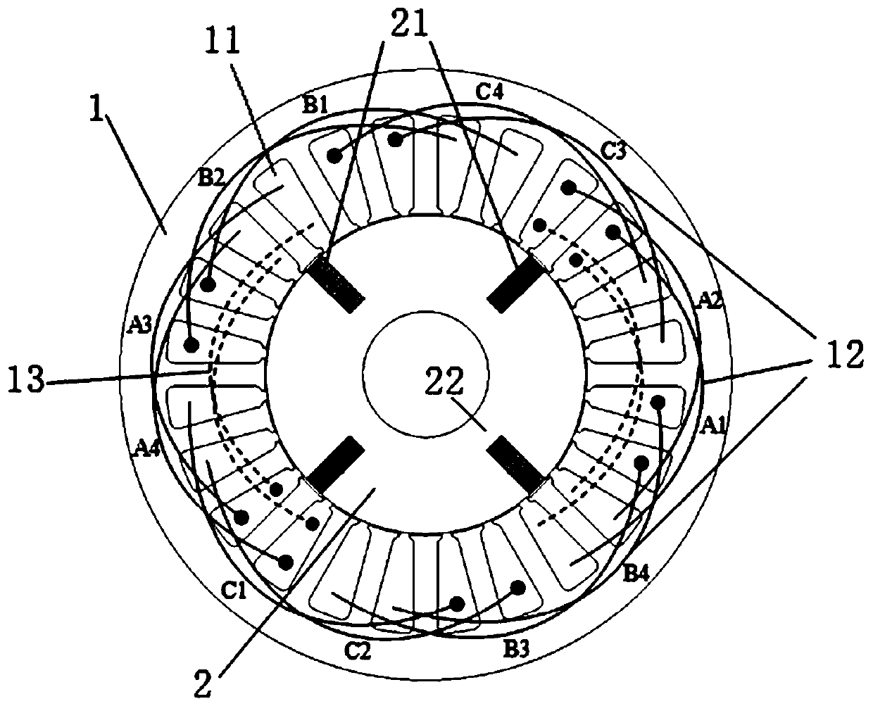
[0049] With three-phase inner rotor motor m=3, N s =24, p =3 as an example, where m represents the number of motor phases, N s Indicates the number of stator slots, and p indicates the number of rotor pole pairs.

[0050] Such as figure 1 As shown, a bilateral excitation type tangential magnetic steel hybrid excitation brushless motor includes a stator 1, a rotor, a tangential magnetic steel 21, a magnetic bridge 22, an armature winding 12 and an excitation winding 13; between the stator and the rotor there is gap.

[0051] In this embodiment, both the stator and the rotor core are preferably made of magnetically permeable materials.

[0052] Both the armature winding and the field winding are AC windings, which are respectively wound on both sides of the stator slot in the stator. The relative winding positions of the armature winding and the field winding can be exchanged, that is, the field winding is outside the slot when the armature winding is inside the slot, or ...

Embodiment 2

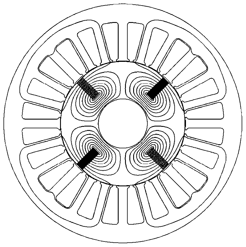
[0064] In Embodiment 1, a magnetic barrier is set on the quadrature-axis magnetic circuit of the rotor to increase the reluctance of the quadrature-axis magnetic circuit, which can reduce the influence of the armature reaction on the AC excitation magnetic field and the permanent magnetic field, thereby improving the output capacity of the motor.

[0065] The magnetic barrier can be a surface quadrature magnetic barrier 23 or a built-in quadrature magnetic barrier. Both the surface quadrature magnetic barrier and the built-in quadrature magnetic barrier are preferably air gaps or non-magnetically conductive materials.

[0066] The magnetic barrier in Embodiment 2 is a surface cross-axis magnetic barrier, which is arranged on the outer surface of the rotor, preferably on the outer surface of the rotor corresponding to the position of the tangential magnetic steel, that is, to increase the air gap of the cross-axis magnetic circuit, as Figure 4 shown.

Embodiment 3

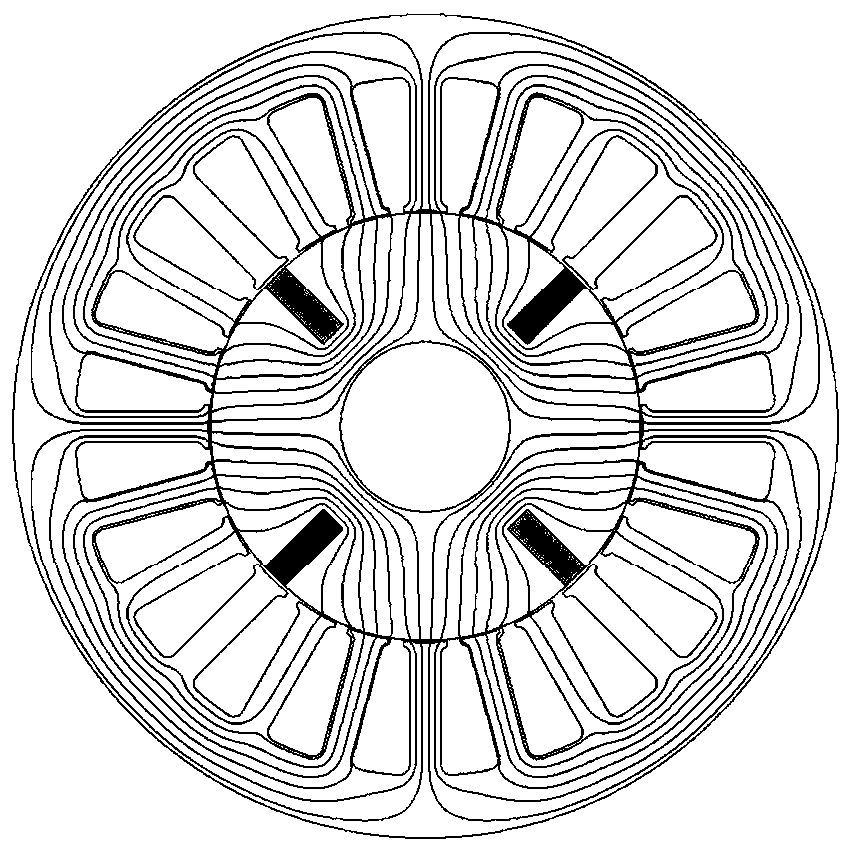
[0068] The magnetic barrier includes both the surface quadrature-axis magnetic barrier and the built-in quadrature-axis magnetic barrier, that is, on the basis of embodiment 2, the built-in quadrature-axis magnetic barrier inside the iron core is added, such as Figure 5 As shown, it is set on the rotor core between two adjacent tangential magnetic steels. Alternatively, the magnetic barrier can also be only a built-in quadrature axis magnetic barrier.


PUM


Abstract

The invention discloses a bilaterally-excited tangential magnetic steel hybrid excited brushless motor, which comprises a stator, a rotor, tangential magnetic steel, magnetic bridges, an armature winding and an excitation winding. The armature winding and the excitation winding are both AC windings and are wound around both sides of a stator slot in the stator respectively, wherein the number of pole pairs of the armature winding is equal to the number of pole pairs of the excitation winding, and is equal to the number of pole pairs of the rotor. The tangential magnetic steel is uniformly embedded in the rotor in the circumferential direction, and the magnetization directions of every two adjacent pieces of tangential magnetic steel are opposite to each other. The magnetic bridges are disposed at the top, the bottom or the middle of each piece of tangential magnetic steel. The brushless motor, by controlling the alternating current of the excitation winding in the stator, generates anexcitation magnetic field synchronously rotating with the rotor so as to realize brushless AC excitation, and adjusts the magnetic field by controlling the magnitude and direction of the excitation component in the excitation winding current, thereby improving the output capacity of the motor and also improving motor space and a material utilization rate.

Description

technical field [0001] The invention relates to the field of motor design, in particular to a bilateral excitation type tangential magnetic steel hybrid excitation brushless motor. Background technique [0002] Permanent magnet motors have the advantages of high torque density, high power density and high efficiency, and have been applied in many occasions. Among them, the magnetic flux of each pole of the tangential magnet steel permanent magnet motor is generated by two tangentially magnetized permanent magnets, which has a magnetic concentration effect, thus having high torque density and permanent magnet material utilization. Nevertheless, field weakening of this motor can only be achieved by applying a negative direct-axis current component in the armature winding (- i d ) to achieve, so that the permanent magnet has the risk of irreversible demagnetization, and the weakening capacity is limited. [0003] The hybrid excitation motor has two magnetic potential sources...

Claims


Application Information

Patent Timeline
Patent Type & Authority Applications(China)
IPC IPC(8): H02K21/14H02K3/12H02K1/27
Inventor 李健王凯刘闯
Owner NANJING UNIV OF AERONAUTICS & ASTRONAUTICS
Why Eureka
Try Eureka