
Thermal conductivity test platform based on visual planar heat pipe and test method thereof

A test platform and test method technology, applied in the direction of measuring device, material thermal development, material excitation analysis, etc., can solve the problem of inaccurate thermal conductivity test, achieve the effect of reducing design test cost, high flow speed, and improving accuracy

Inactive Publication Date: 2019-07-02
PEKING UNIV
View PDF5 Cites 1 Cited by
  • Summary
  • Abstract
  • Description
  • Claims
  • Application Information

AI Technical Summary

Problems solved by technology

[0004] In view of the above-mentioned deficiencies, the present invention provides a thermal conductivity testing platform and testing method based on a visualized planar heat pipe, which is used to solve the inaccurate problem of the thermal conductivity test of the existing planar heat pipe under non-visualized conditions; In order to visualize the upper end surface, the effect of choosing different micro-column structures and bottom-end materials on the overall thermal conductivity of the planar heat pipe is adopted; after the micro-column structure is processed, the glass plate is used for bonding, so that the planar heat pipe is sealed and the internal structure is visible. , can more intuitively analyze the relationship between vapor-liquid phase transition and heat flow input, and has very practical significance for the design of planar heat pipes

Method used


Image

  • Thermal conductivity test platform based on visual planar heat pipe and test method thereof
  • Thermal conductivity test platform based on visual planar heat pipe and test method thereof
  • Thermal conductivity test platform based on visual planar heat pipe and test method thereof

Examples


Embodiment Construction

[0049] For a better understanding, the embodiments of the present invention are explained in detail with reference to the accompanying drawings.

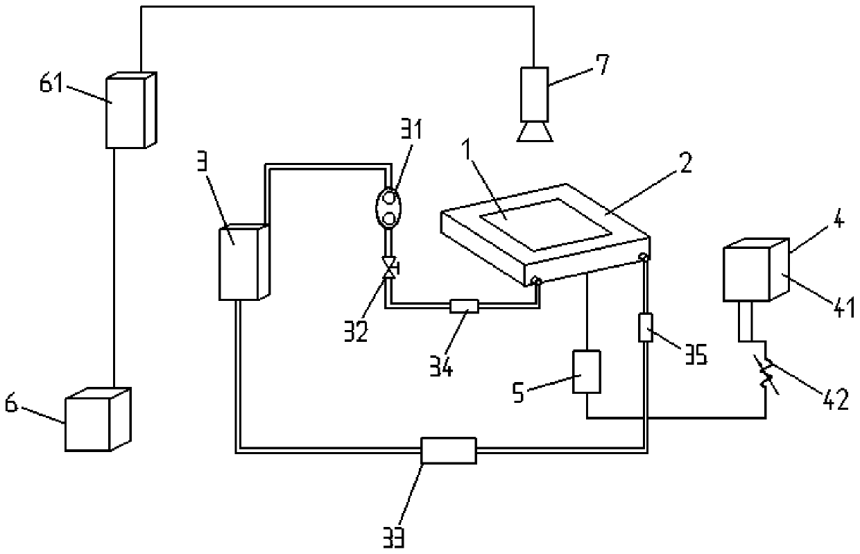
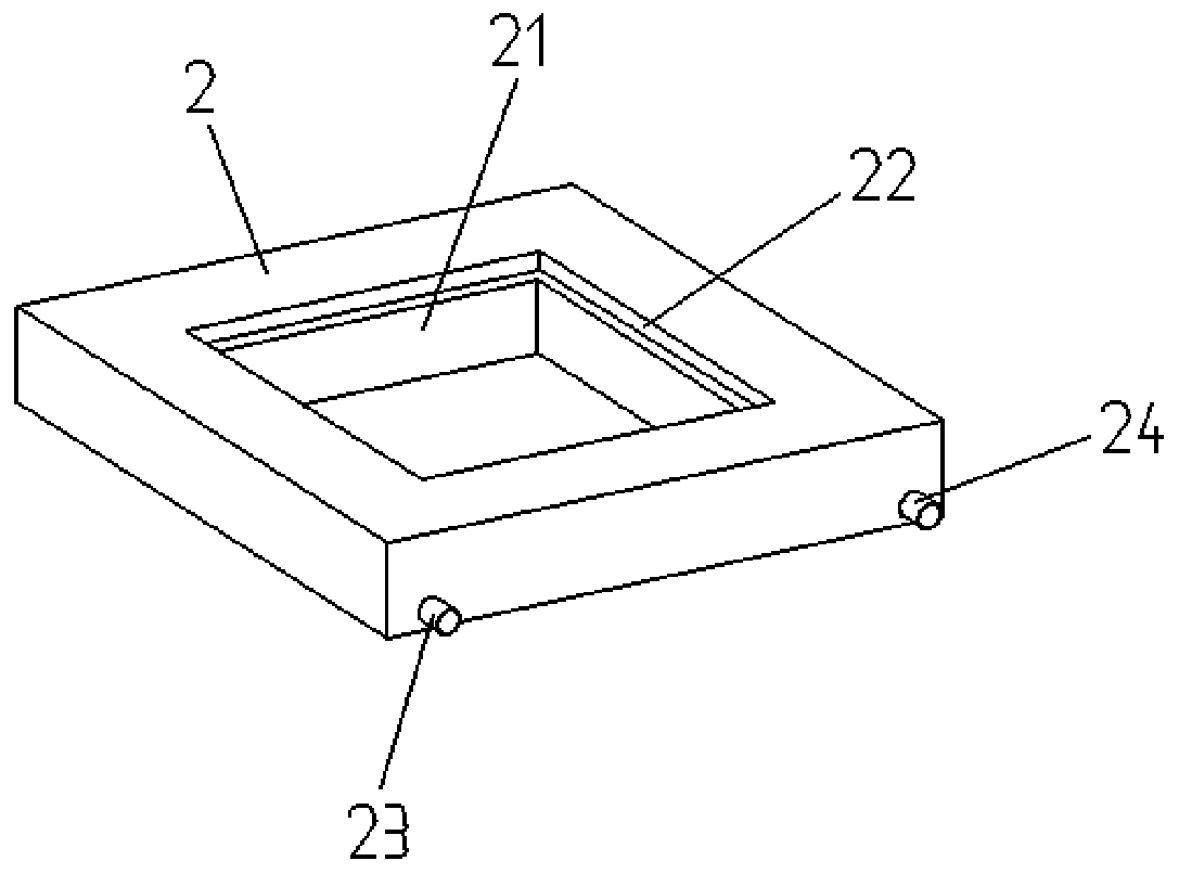
[0050] Such as Figures 1 to 4 As shown, a thermal conductivity test platform based on a visual planar heat pipe includes a working module and a measurement module. The working module and the measurement module are arranged separately. Base diode 8, constant current voltage source 4, programmable relay 5 and cooling water tower 3;

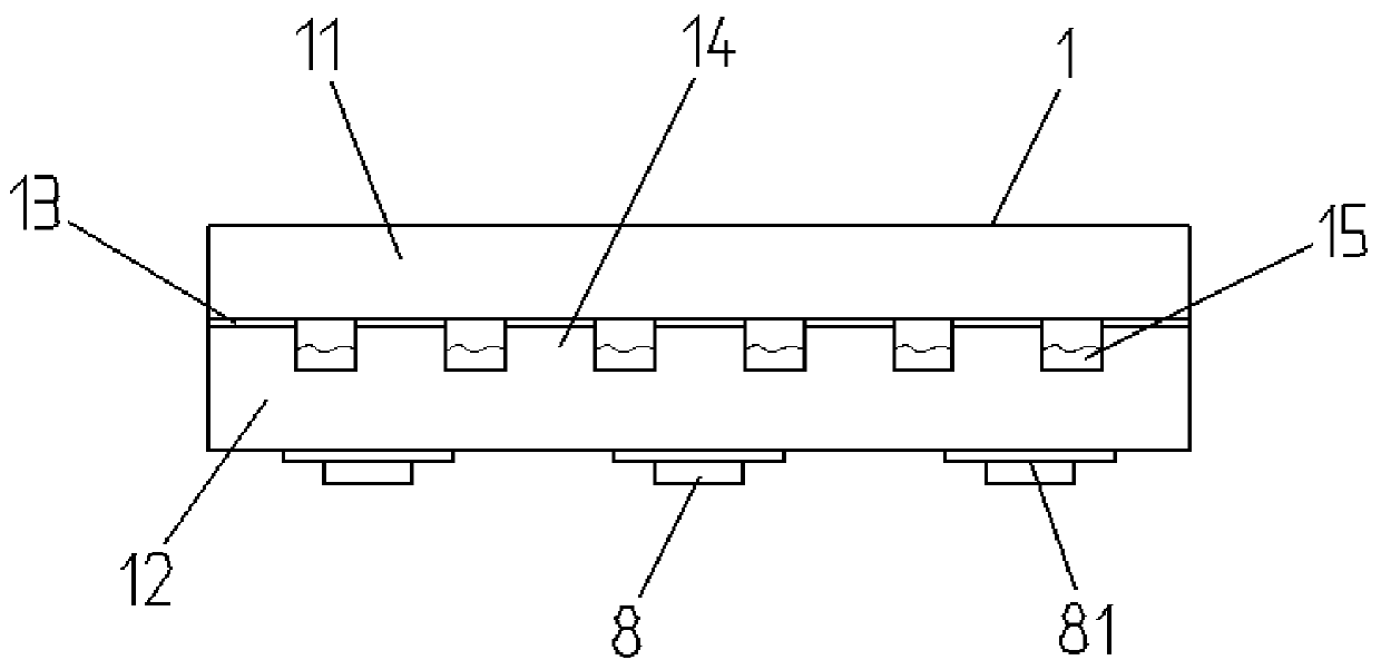
[0051] The planar heat pipe 1 includes a 0.35 mm thick SiC wafer 12 arranged at the bottom, a plurality of hexagonal micropillars 14 uniformly etched on the SiC wafer 12, and a heat exchange working fluid 15 located outside the hexagonal micropillars 14 And the 0.5mm thick glass wafer 11 on the top, the glass wafer 11 is combined with the SiC wafer 12 using a gold-gold bonding process with a gold coating 13 of 2 μm, and the hexagonal micropillars 14 are evenly arranged in a honeycomb shape;

[0052] Th...


PUM


Abstract

The invention provides a thermal conductivity test platform based on a visual planar heat pipe and a test method thereof, which belong to the technical field of planar heat pipes. The platform comprises a working module and a measuring module, wherein the working module and the measuring module are arranged separately. The working module comprises an aluminum radiator, a cooling water tower connected with the aluminum radiator, the planar heat pipe arranged on the aluminum radiator, a Schottky diode arranged at the bottom of the planar heat pipe, and a constant current voltage source electrically connected with the Schottky diode. The measuring module comprises a data acquisition module, a data conversion module electrically connected with the data acquisition module, and a data processingmodule. The data acquisition module is correspondingly arranged directly above the planar heat pipe. The platform is used to solve the problem of inaccurate thermal conductivity test of the existingplanar heat pipe under the condition of non-visualization. Through a visual test before the manufacture of the heat pipe, the radiation range of a heat source and the heat flux density of a working medium entering the nuclear boiling state can be known. The design and test cost of the planar heat pipe can be greatly reduced.

Description

technical field [0001] The invention relates to a thermal conductivity test platform based on a visualized planar heat pipe and a test method thereof, belonging to the technical field of planar heat pipes. Background technique [0002] At present, with the continuous development of integrated circuits, the heat dissipation of high-power devices cannot be ignored. Planar heat pipes are one of the most effective and compact passive two-phase cooling systems suitable for heat dissipation in small electronic systems. Compared with other heat dissipation systems, planar heat pipes Heat pipes have a greater advantage in manufacturing. In the prior art, in order to improve the heat dissipation capacity of the planar heat pipe, various internal structures have been proposed to improve the heat dissipation, which mainly include the micro-column structure and the material selection of the thermal contact end. However, due to the limitation of the experimental conditions, it is difficu...

Claims


Application Information

Patent Timeline
IPC IPC(8): G01N25/20G01N21/65G01N21/84
CPCG01N21/65G01N21/84G01N25/20G01N2021/8416
Inventor 王振宇高蓉余汇宇
Owner PEKING UNIV
Learn More