
Recycling cooling backwater surplus energy utilization process and facility

A technology of circulating cooling and surplus energy, which is applied in water shower coolers, mechanical equipment, hydroelectric power generation, etc., which can solve the lack of supplementary air and cooling fluid circulation functions, the inability to ensure the effective use of water resources and surplus power, and heat exchange components Issues such as less publicity, to achieve the effect of reducing manual duty, saving energy consumption, and saving electricity

Pending Publication Date: 2019-07-05
NANTONG CELLULOSE FIBERS CO LTD
View PDF0 Cites 0 Cited by
  • Summary
  • Abstract
  • Description
  • Claims
  • Application Information

AI Technical Summary

Problems solved by technology

This invention has little disclosure on the heat exchange components, lacks the functions of supplementary air and cooling liquid circulation, and cannot guarantee the effective use of water resources and surplus power

Method used


Image

  • Recycling cooling backwater surplus energy utilization process and facility
  • Recycling cooling backwater surplus energy utilization process and facility

Examples


Embodiment 1

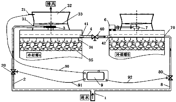
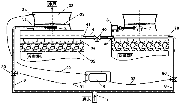
[0028] like figure 1 The cooling tower residual pressure utilization facility has a water inlet main pipe, a branch A, a branch B, a cooling tower A, and a cooling tower B, and the water inlet main pipe is respectively connected to the branch A and the branch B, and the branch A is connected to the cooling tower The water inlet A of A, the branch A is provided with a control valve A, the branch B is connected to the water inlet B of the cooling tower B, the branch B is provided with a control valve B, and the fan impeller at the top of the cooling tower A has a common rotating shaft. Water turbine impeller, cooling tower A is provided with a rotating speed measuring device for measuring the water turbine impeller.

[0029] There is a reducer with a common shaft under the fan impeller on the top of cooling tower B, and the reducer is connected and driven by a motor; in addition, there is a controller; there is a control line between the controller and the control valve A, which...


PUM


Abstract

The invention introduces a circulating cooling backwater surplus energy utilization facility. The circulating cooling backwater surplus energy utilization facility is provided with a water inlet totalpipe, a branch A, a branch B, a cooling tower A and a cooling tower B, wherein the cooling tower A is provided with a rotating speed measuring device, the lower portion of an air fan impeller at an air exhaust mouth of the cooling tower A is provided with a water turbine impeller with a shared rotating shaft, and two water tanks of the two cooling towers are controlled and connected through a water distribution tank communicating pipe and a communicating valve. A control method for the circulating cooling backwater surplus energy utilization facility is that the opening and closing degree ofan adjusting and control valve A and an adjusting and control valve B is controlled correspondingly, sufficient circulation cooling backwater is made to enter the branch A to provide sufficient waterpower for a water turbine, the water turbine and tower top fan blades are pushed to rotate, and the designed cooling effect is achieved without power consumption. By means of the circulating cooling backwater surplus energy utilization facility, circulating cooling backwater surplus energy is utilized sufficiently, a motor is entirely replaced to push the fan blades to rotate, electricity consumption is saved, and the self-control degree is relatively high.

Description

technical field [0001] The invention relates to the structure and operation technology of a cooling tower. Background technique [0002] The cooling tower usually uses cold air to cool the hot water, and the cooled solution flows into the bottom of the cooling tower, and the hot air is discharged from the top of the cooling tower by the fan. In the past, the fan blades of the motor-driven fan have been used to rotate the exhaust air. [0003] The invention with patent application number 2012100232870 discloses a cross-flow cooling tower, which includes a tower body, an air inlet and an air outlet. The fan is equipped with a spraying device on the upper part of the tower body. The spraying device is connected to the water pipe. A water tank is installed at the bottom of the tower body. The lower end of the water pipe extends into the water tank. The induced draft fan of the air outlet of the invention needs to consume extra energy. [0004] The invention with the patent ap...

Claims


Application Information

Patent Timeline
Patent Type & Authority Applications(China)
IPC IPC(8): F28C1/00F28F27/02F03B13/00F03B15/06
CPCF28C1/00F28F27/02F03B13/00F03B15/06Y02E10/20
Inventor 李晓东高勇郭叶书朱建华
Owner NANTONG CELLULOSE FIBERS CO LTD
Learn More