Array antenna

An array antenna and antenna sub-technology, applied in antennas, resonant antennas, antenna arrays, etc., can solve problems such as reducing antenna gain, increasing insertion loss, and transforming transmission line impedance

Inactive Publication Date: 2019-07-05
CHINA COMM MICROELECTRONICS TECH CO LTD
View PDF14 Cites 7 Cited by
  • Summary
  • Abstract
  • Description
  • Claims
  • Application Information

AI Technical Summary

Problems solved by technology

[0003] For the millimeter wave working frequency band, the frequency is high and limited by the antenna processing technology and materials, the insertion loss of the transmission line cannot be ignored, especially for the array antenna composed of multiple array elements to improve the gain, the parallel feed network will also become very Huge, one is that the insertion loss becomes larger due to the length of the transmission line, and the other is that the transmission line needs to be bent or impedance transformed many times, resulting in a discontinuous impedance that causes the insertion loss to increase
Although parallel feeding reduces antenna bandwidth loss, it brings radiation efficiency loss and reduces antenna gain
[0004] Another method that can effectively increase the antenna bandwidth is to greatly increase the dielectric thickness of the microstrip antenna. However, an overly thick substrate will obtain a surface wave mode, especially when the dielectric constant of the dielectric plate is large, which is more difficult than the basic work. The mode with a higher mode will be excited, resulting in distortion of the pattern, and a larger back lobe, resulting in less obvious beam focusing effect and reducing the overall gain of the antenna

Method used


Image

  • Array antenna
  • Array antenna
  • Array antenna

Examples


Embodiment Construction

[0027] In order to facilitate the understanding of the present application, the present application will be described more fully below with reference to the relevant drawings. Preferred embodiments of the application are shown in the accompanying drawings. However, the present application can be embodied in many different forms and is not limited to the embodiments described herein. On the contrary, the purpose of providing these embodiments is to make the disclosure of the application more thorough and comprehensive.

[0028] It should be noted that when an element is referred to as being “fixed” to another element, it can be directly on the other element or there can also be an intervening element. When an element is referred to as being "connected to" another element, it can be directly connected to the other element or intervening elements may also be present. The terms "vertical," "horizontal," "left," "right," and similar expressions are used herein for purposes of ill...


PUM


Abstract

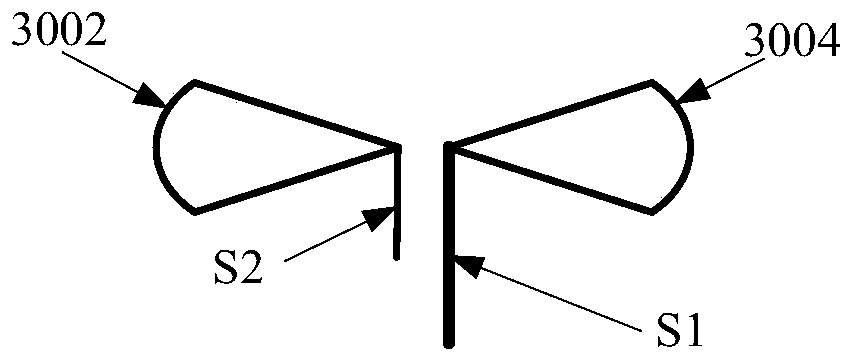
The invention relates to an array antenna, which comprises a dielectric substrate, a reference formation and a dipole antenna array, wherein the reference formation is arranged at the back side of thedielectric substrate; the dipole antenna array is arranged at the front side of the dielectric substrate, and comprises a first antenna array element and a second antenna array element in parallel arrangement; each of the first antenna array element and the second antenna array element comprises a plurality of dipole units which are arranged at equal intervals and are connected in series; each dipole unit in the first antenna array element is in relative arrangement to each dipole unit in the second antenna array element; each dipole unit is connected with the reference formation; each dipoleunit realizes the power feed through a microstrip transmission line or coplanar waveguide; the dipole antenna array also comprises a line feeder arranged between the first antenna array element and the second antenna array element; and the line feeder is used for connecting the first antenna array element and the second antenna array element. By using a mode of combining the serial connection power feed and the parallel connection power feed, the insertion loss of a feed network can be reduced; and the antenna gain is ensured.

Description

technical field [0001] The present invention relates to the technical field of antennas, in particular to an array antenna. Background technique [0002] For array antennas, there are generally two feeding methods: series feeding and parallel feeding. The so-called series feeding means that the antenna units are connected in series. length) to achieve the same excitation phase, so once the frequency shifts, the phase shift of each unit is different, the beam pointing is different, and the antenna bandwidth will be relatively narrow; and the parallel feed can achieve the same path from the feed point to each antenna unit, and each unit The phase can be guaranteed not to change with the frequency, and the beam pointing remains unchanged, so the bandwidth is wide. [0003] For the millimeter wave working frequency band, the frequency is high and limited by the antenna processing technology and materials, the insertion loss of the transmission line cannot be ignored, especially...

Claims


Application Information

Patent Timeline
Patent Type & Authority Applications(China)
IPC IPC(8): H01Q19/10H01Q21/00H01Q21/08H01Q9/28H01Q1/38H01Q1/48H01Q1/50
CPCH01Q1/38H01Q1/48H01Q1/50H01Q9/285H01Q19/104H01Q21/00H01Q21/0006H01Q21/08
Inventor 万志明丁曙煜
Owner CHINA COMM MICROELECTRONICS TECH CO LTD
Why Eureka
Try Eureka