Fiber-metal composite laminate, forming die therefor and forming method

A technology of fiber metal and forming molds, applied in the direction of metal layered products, other household appliances, chemical instruments and methods, etc., can solve the problems of long preparation cycle, low production efficiency, long-time curing, etc., and achieve improved forming accuracy and forming Quality, improvement of production efficiency and quality, effect of reducing forming process

Active Publication Date: 2019-07-09
CENT SOUTH UNIV
View PDF6 Cites 19 Cited by
  • Summary
  • Abstract
  • Description
  • Claims
  • Application Information

AI Technical Summary

Problems solved by technology

[0003] The existing carbon fiber-aluminum alloy composite laminates are laminated alternately by directly laying carbon fibers and aluminum alloys, or alternately laying carbon fibers, thermosetting adhesive films, and aluminum alloys. Due to the high temperature fluidity of the thermosetting resin matrix , The flow of the resin is disordered during molding, which is prone to internal defects, and the thermosetting resin needs to be cured for a long time after molding, and cross-linking and curing reactions occur, resulting in low production efficiency
Existing carbon fiber-aluminum alloy composite laminates are generally formed by autoclave, which has low forming efficiency, long preparation cycle, and simple forming shape, which is not suitable for high-efficiency and low-cost manufacturing; while the traditional molding method separates the heating and forming processes, There are many manufacturing processes, which affect the preparation efficiency. At the same time, it is easy to crack during hot stamping and forming, and the formability is poor
Moreover, there is a relatively serious potential corrosion problem between the aluminum alloy and the carbon fiber in the existing carbon fiber-aluminum alloy composite laminate, which restricts its further development.

Method used


Image

  • Fiber-metal composite laminate, forming die therefor and forming method
  • Fiber-metal composite laminate, forming die therefor and forming method
  • Fiber-metal composite laminate, forming die therefor and forming method

Examples


Embodiment 1

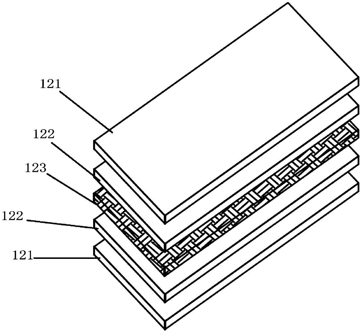
[0033] Such as figure 1 As shown, the fiber metal composite laminate in this embodiment includes two aluminum alloy layers 121, two PEEK resin layers 122 are arranged between the two aluminum alloy layers 121, and a carbon fiber pre-layer is arranged between the two PEEK resin layers 122. Dip layer 123 .

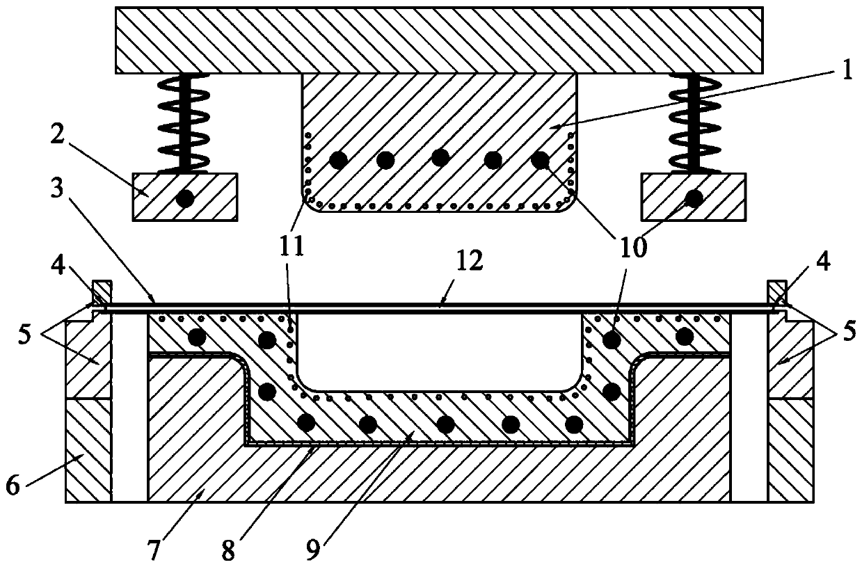
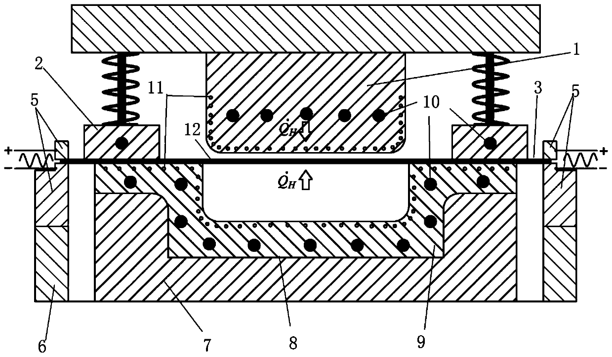
[0034] Such as Figure 2-4 As shown, this embodiment also provides a fiber metal composite laminate forming die for making the above fiber metal composite laminate, including a correspondingly arranged punch 1 and a combined die, the punch 1 is located above the combined die, and the combined The die comprises a lower die 7 and an upper die 9 arranged on the lower die 7, an insulating layer 8 is arranged between the upper die 9 and the lower die 7, the bottom of the punch 1 and the top of the upper die 9 A number of water passage holes 11 are evenly arranged respectively; the side of the punch 1 is provided with a blank holder 2, and the blank holder 2 includes a blank hol...


PUM


Abstract

The invention discloses a fiber-metal composite laminate, a forming die therefor and a forming method. The fiber-metal composite laminate comprises two aluminum-alloy layers, wherein at least two PEEKresin layers are arranged between the two aluminum-alloy layers, and a carbon fiber prepreg layer is arranged between every two adjacent PEEK resin layers. The forming die for the fiber-metal composite laminate comprises a male die and a combined female die which are arranged correspondingly. The forming method for the fiber-metal composite laminate comprises the step of carrying out hot stampingforming on the fiber-metal composite laminate by using the forming die. According to the fiber-metal composite laminate, the forming die therefor and the forming method, disclosed by the invention, the efficiency and quality of production of the fiber-metal composite laminate are improved.

Description

technical field [0001] The invention relates to the technical field of composite laminates, in particular to a fiber metal composite laminate, a forming die and a forming method thereof. Background technique [0002] The aluminum alloy thin plate and carbon fiber reinforced composite material are solidified and formed under a certain temperature and pressure according to a specific lamination method. The formed fiber-metal composite laminate not only has high specific strength and specific stiffness, but also has very Good impact resistance, crack growth resistance and environmental corrosion resistance, etc., have broad application prospects in aerospace, military weapons, high-speed vehicles and other fields. [0003] The existing carbon fiber-aluminum alloy composite laminates are laminated alternately by directly laying carbon fibers and aluminum alloys, or alternately laying carbon fibers, thermosetting adhesive films, and aluminum alloys. Due to the high temperature fl...

Claims


Application Information

Patent Timeline
Patent Type & Authority Applications(China)
IPC IPC(8): B32B27/28B32B27/12B32B27/06B32B15/20B32B15/08B32B9/04B32B9/00B29C70/46B29C70/44
CPCB29C70/44B29C70/46B29L2007/002B29L2009/00B32B5/02B32B9/045B32B15/08B32B15/20B32B27/06B32B27/12B32B27/288B32B2250/40B32B2260/021B32B2262/106
Inventor 李毅波潘晴黄明辉刘峙麟陈超
Owner CENT SOUTH UNIV
Why Eureka
Try Eureka