Manufacturing method of PVC floor tile, PVC floor tile and manufacturing equipment
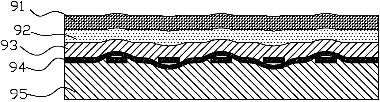
A production method and floor tile technology, applied in chemical instruments and methods, lamination auxiliary operations, lamination, etc., can solve the problems affecting the appearance and performance of PVC floor tiles, the downward movement of the printing layer 92 is blocked, and the fusion is hindered.
- Summary
- Abstract
- Description
- Claims
- Application Information
AI Technical Summary
Problems solved by technology
Method used
Image

Examples
Embodiment Construction
[0027] In order to further explain the technical means and functions adopted by the present invention to achieve the intended invention purpose, the detailed description is as follows in conjunction with the accompanying drawings and preferred embodiments.
[0028] The invention provides a method for making PVC (Polyvinyl chloride; polyvinyl chloride) floor tiles, PVC floor tiles and production equipment. According to the method for making PVC floor tiles, the impact of the glass fiber layer on the printing layer can be reduced when the PVC floor tiles are pressed. Effect, prevents fiberglass screen printing on the printed layer.
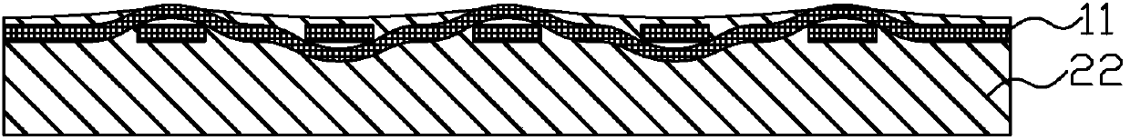
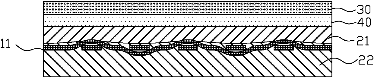
[0029] Figure 2a to Figure 2b It is a structural schematic diagram of each step in the production method of PVC floor tiles provided by the first embodiment of the present invention. like Figure 2a to Figure 2b Shown, in the present embodiment, the manufacture method of the PVC floor tile provided by the invention comprises the steps:
[0030] ...
PUM
 Abstract
Description
Claims
Application Information