
A Power Grid Control Method Based on Quasi-Z Source Three-Level Inverter

A technology of a three-level inverter and a control method, which is applied in the field of quasi-Z sources, and can solve problems such as increasing the through time, high capacitor voltage stress, and increasing capacitor voltage stress

Active Publication Date: 2020-10-23
SHANGHAI UNIVERSITY OF ELECTRIC POWER
View PDF3 Cites 0 Cited by
  • Summary
  • Abstract
  • Description
  • Claims
  • Application Information

AI Technical Summary

Problems solved by technology

However, the existing Z-source inverter topology has limitations: the DC boost factor is small, and when the output voltage is high, the through time must be increased, making the inverter in a harsh working environment for a long time, which also increases the capacitor voltage stress ;The starting surge current is too large, which may easily damage the inverter
There is also an improved Z-source inverter that specifically proposes to increase the boosting capacity, but the boosting effect is not obvious
In addition, the switched inductor technology is applied to the Z-source topology, and the symmetrical two-level structure adopted, the capacitor voltage stress is still high, and the voltage intensity of the switching device is still very large.

Method used


Image

  • A Power Grid Control Method Based on Quasi-Z Source Three-Level Inverter
  • A Power Grid Control Method Based on Quasi-Z Source Three-Level Inverter
  • A Power Grid Control Method Based on Quasi-Z Source Three-Level Inverter

Examples


Embodiment

[0053] The present invention analyzes the structure and working principle of the traditional Z-source three-level inverter, applies the switching inductance technology to the Z-source network topology, and adopts a symmetrical structure to introduce simple boost control into the quasi-Z-source three-level inverter device.

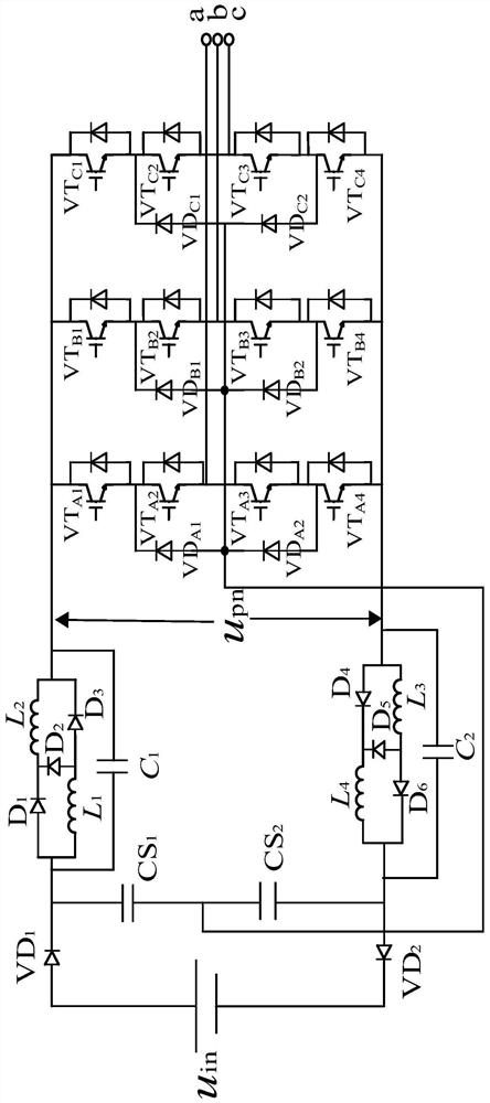
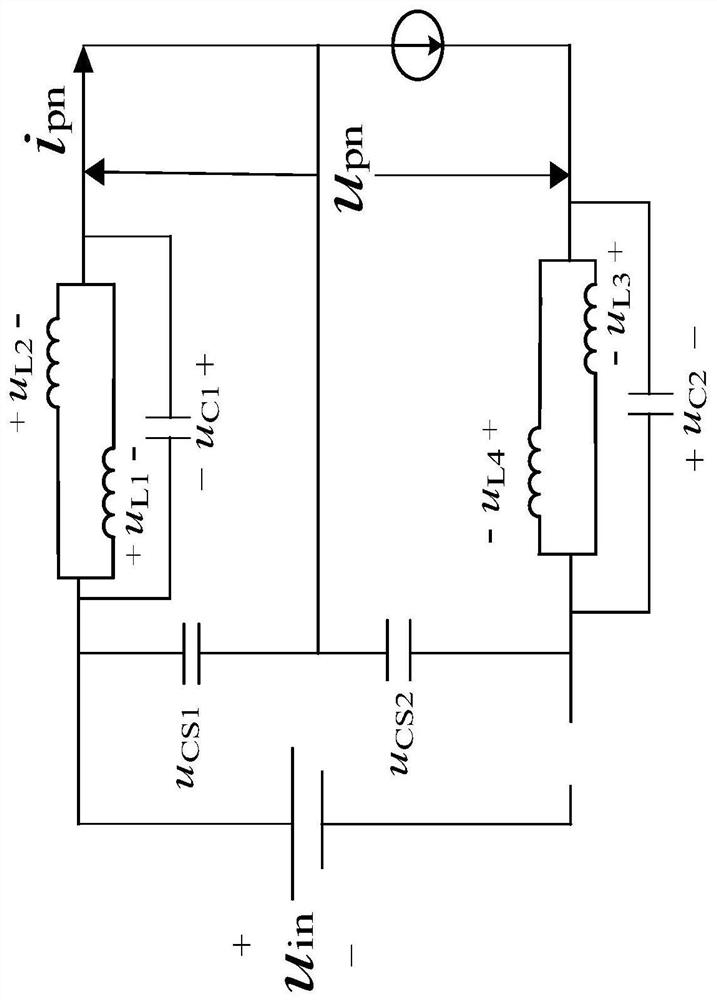
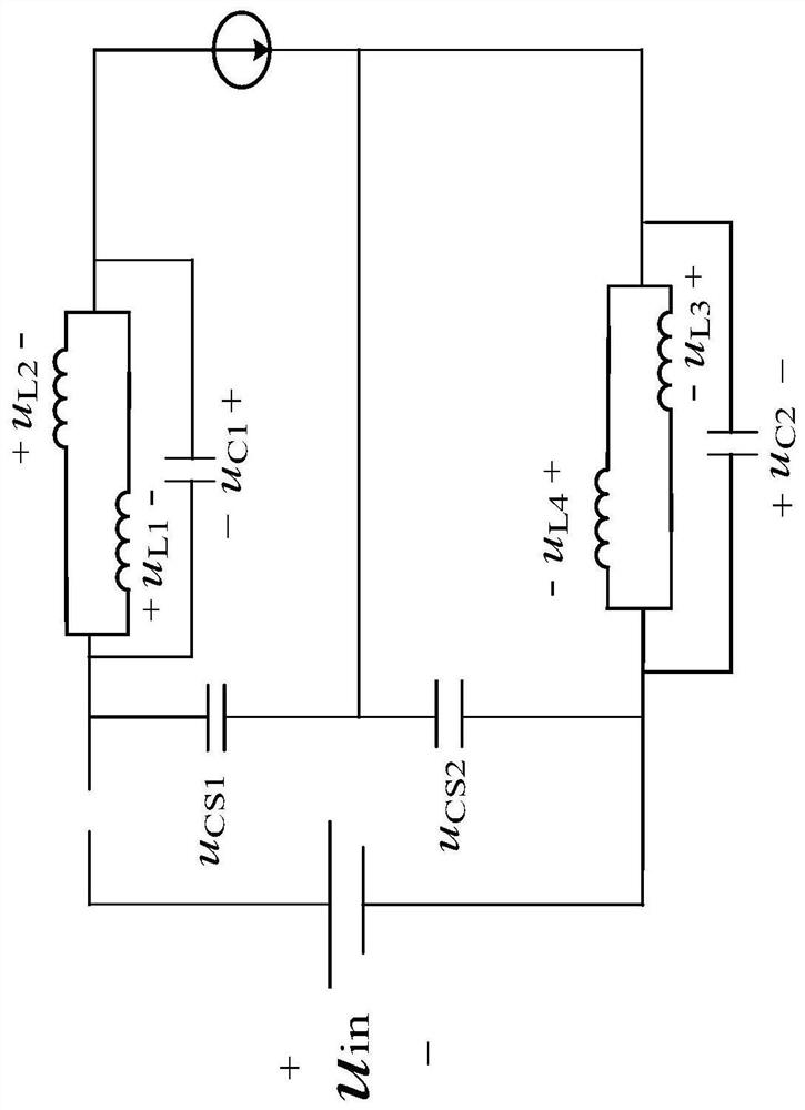
[0054] figure 1 It is the topological structure of the quasi-Z source three-level inverter described in the present invention. This inverter topology uses only one voltage u in DC input power supply, C s1 and C s2 is the voltage divider capacitor, and C s1 =C s2 , a quasi-Z source network is connected between the voltage dividing capacitor and the traditional three-level inverter, u pn Output DC link peak voltage for Z source network. The quasi-Z source network part consists of 4 inductors (L 1 ~ L 4 ), 2 capacitors (C 1 ~C 2 ) and 8 diodes (D 1 ~D 6 , VD 1 and VD 2 )composition. L 1 ~ L 2 、D 1 ~D 3 The inductance unit of the first switc...


PUM


Abstract

The invention relates to a grid control method based on a quasi-Z-source three-level inverter. The grid control method comprises the following steps: step 1: the DC state equation of a static workingpoint time system is established according to the topology structure of the quasi-Z-source three-level inverter; step 2, a state variable including the disturbance amount is added to the DC state equation to obtain a small-signal dynamic equation model of the quasi-Z-source three-level inverter topology structure under Laplace transformation; and step 3, the grid-related voltage is dynamically controlled by adjusting the topological structure relate parameters of the quasi-Z-source three-level inverter. Compared with the methods in the prior art, the grid control method has the characteristicsof high voltage boosting capability, obvious reduction of capacitance voltage stress, simple and clear control system, easy realization and the like.

Description

technical field [0001] The invention relates to the field of quasi-Z source technology, in particular to a grid control method based on a quasi-Z source three-level inverter. Background technique [0002] In recent years, with the rapid development of microgrid technology and the wide application of new energy sources, new inverter topologies and their modeling analysis have become a research hotspot. The proposal of the Z-Source Inverter (ZSI) makes the straight-through of the upper and lower bridge arms a normal state, forming a unique buck-boost mechanism, which increases system security and anti-electromagnetic interference. However, the existing Z-source inverter topology has limitations: the DC boost factor is small, and when the output voltage is high, the through time must be increased, making the inverter in a harsh working environment for a long time, which also increases the capacitor voltage stress ; If the starting surge current is too large, the inverter may b...

Claims


Application Information

Patent Timeline
Patent Type & Authority Patents(China)
IPC IPC(8): H02M7/537H02M7/483H02J3/38
CPCH02J3/38H02M7/483H02M7/537
Inventor 程启明沈磊魏霖王玉娇程尹曼
Owner SHANGHAI UNIVERSITY OF ELECTRIC POWER
Learn More