
Distributed optical fiber sensing system based on mode coupling

A distributed optical fiber, sensing system technology, applied in the direction of measurement, instrument, measurement force, etc. by measuring the change of optical properties of materials when they are stressed, can solve the problems of inability to measure radial stress along the optical fiber and high measurement accuracy , to achieve the effect of simple structure, low energy consumption, high sensitivity and high precision measurement

Active Publication Date: 2019-07-12
PEKING UNIV
View PDF12 Cites 7 Cited by
  • Summary
  • Abstract
  • Description
  • Claims
  • Application Information

AI Technical Summary

Problems solved by technology

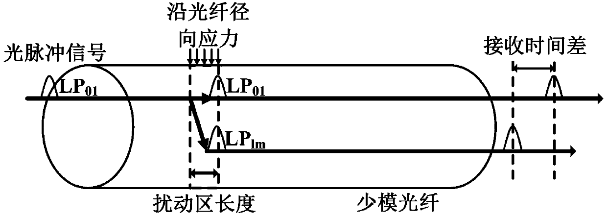
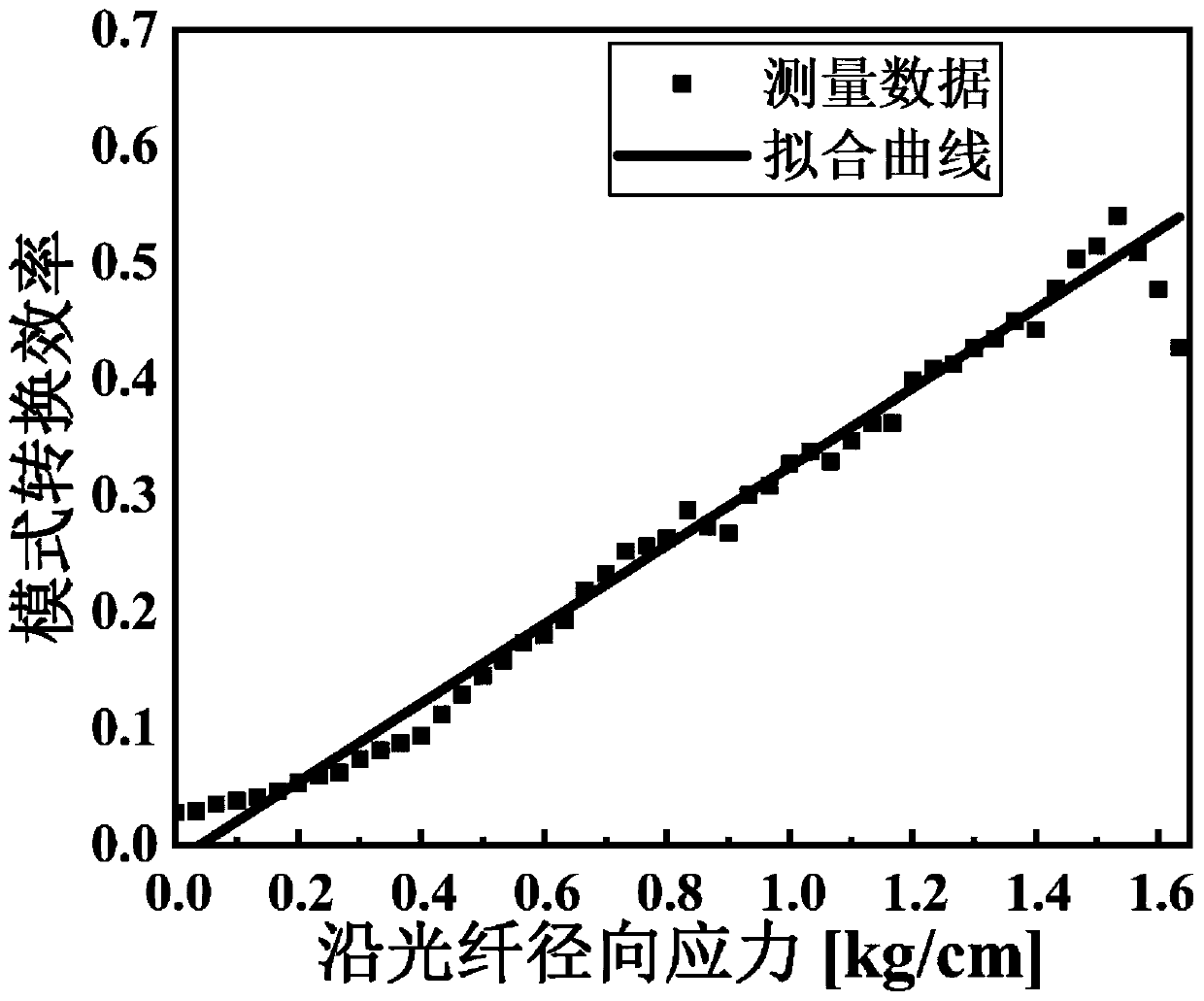
[0008] In view of the problems existing in the prior art, the purpose of the present invention is to provide a distributed optical fiber sensing system and method based on mode coupling, which can solve the problem that the existing technology cannot measure the radial stress of the optical fiber at any angle, and compared with the market The existing distributed sensing system has the advantages of high sensitivity to radial stress along the optical fiber and high measurement accuracy

Method used


Image

  • Distributed optical fiber sensing system based on mode coupling
  • Distributed optical fiber sensing system based on mode coupling
  • Distributed optical fiber sensing system based on mode coupling

Examples


Embodiment Construction

[0027] In order to make the object, technical solution and advantages of the present invention clearer, the present invention will be further described in detail below in conjunction with the accompanying drawings and embodiments. It should be understood that the specific embodiments described here are only used to explain the present invention, not to limit the present invention.

[0028] The present invention proposes a distributed optical fiber sensing system and method based on mode coupling, which can solve the problem that the existing technology cannot measure the radial stress along the optical fiber at any angle, and at the same time, compared with the existing distributed sensing system on the market, it has the advantages of The advantages of high stress sensitivity and high measurement accuracy along the fiber radial direction. Specifically, the mode-coupling-based distributed optical fiber sensing system and method provided by the present invention have the follow...


PUM

PropertyMeasurementUnit
lengthaaaaaaaaaa

Abstract

The invention discloses a distributed optical fiber sensing system based on mode coupling. The distributed optical fiber sensing system based on mode coupling is characterized by comprising, at a transmitting end and a receiving end, a few-mode fiber which has the length of L, wherein the transmitting end and the receiving end are connected through the few-mode fiber of which the length is L, andthe transmitting end is used for generating a pulsed light and injecting into a basic mode of the few-mode fiber; the receiving end is used for receiving an optical signal of the a few-mode fiber andconverting the optical signal into an electric signal; repetition frequency of the pulsed light is R and pulse width of the pulsed light is T; Formula (represented by a formula in specification), T isgreater than or equal to 1ps and less than or equal to 1ns, Tau<DMD> refers to differential mode group delay between the basic mode of the few-mode fiber and the highest order mode supported by the few-mode fiber. The distributed optical fiber sensing system based on mode coupling provided by the invention can realize high sensitivity and high precision measurement for optical fiber radial stress, and also can provide measurement of stress of any angle along an optical fiber radial direction, and has important significance in actual use.

Description

technical field [0001] The invention belongs to the technical field of distributed optical fiber sensors, and relates to a distributed optical fiber sensing system and method based on mode coupling. Background technique [0002] Due to its wide detection range and low cost, distributed optical fiber sensing has attracted more and more attention, and has important applications in geological disaster prediction, structural health monitoring, and perimeter security. Distributed optical fiber sensors can detect physical quantities such as vibration, temperature, axial stress along the optical fiber, and radial stress (pressure) along the optical fiber distributed along the optical fiber cable, and have a good market prospect. [0003] At present, the common distributed optical fiber sensing measurement system is based on the principle of backscattering, which realizes detection by changing the properties of scattered light, such as phase, polarization and frequency. Specific im...

Claims


Application Information

Patent Timeline
Patent Type & Authority Applications(China)
IPC IPC(8): G01L1/24
CPCG01L1/242
Inventor 李巨浩贾骏驰何永琪陈章渊
Owner PEKING UNIV
Learn More