
TOF module for VSLAM system and VSLAM calculation method

A calculation method and module technology, applied in stereoscopic systems, radio wave measurement systems, using re-radiation, etc., can solve the problems of short shooting distance, single function, poor precision, etc., and achieve the effect of good performance

Active Publication Date: 2019-07-12
UNRE SHANGHAI INFORMATION TECH CO LTD
View PDF7 Cites 3 Cited by
  • Summary
  • Abstract
  • Description
  • Claims
  • Application Information

AI Technical Summary

Problems solved by technology

[0007] The technical problem to be solved by the present invention is to overcome the defects of short shooting distance, poor precision and single function in the TOF module in the prior art, and provide a method capable of shooting objects at a longer distance, with better imaging effect and lower manufacturing cost. Inexpensive, easy to produce, in addition, this application also has night vision function, user-friendly TOF module and VSLAM calculation method for VSLAM system

Method used


Image

  • TOF module for VSLAM system and VSLAM calculation method
  • TOF module for VSLAM system and VSLAM calculation method
  • TOF module for VSLAM system and VSLAM calculation method

Examples


Embodiment 1

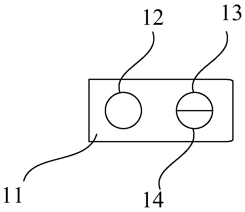
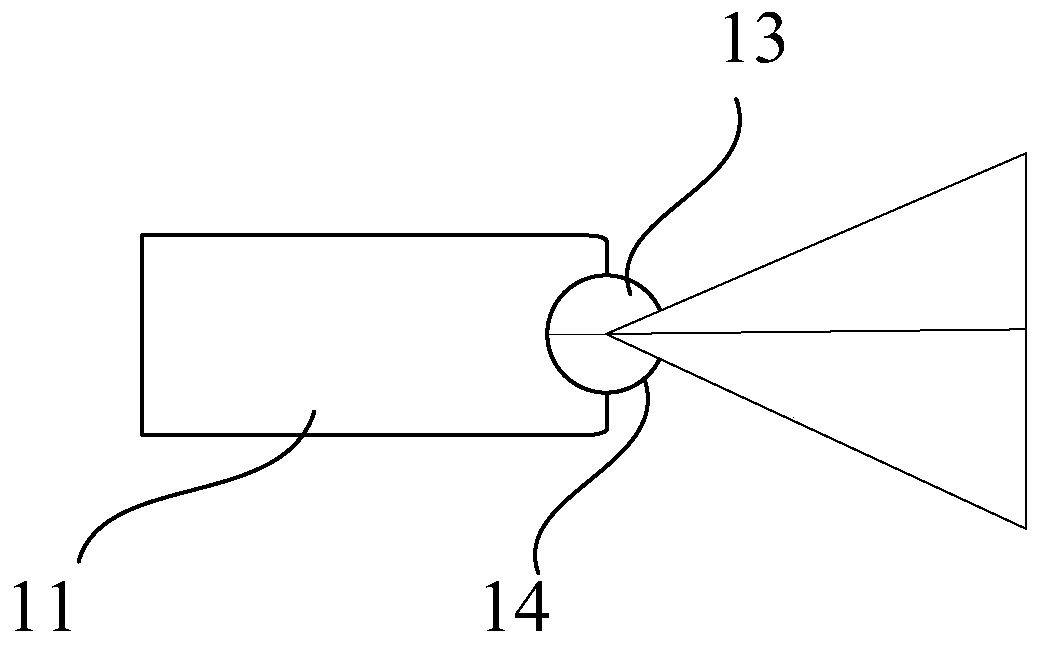
[0050] see figure 1 , figure 2 , this embodiment provides a TOF module for a VSLAM system.

[0051] The TOF module 11 includes at least one light source 12, and the TOF module also includes at least one imaging unit and a synchronization unit for synchronizing the light source and the imaging unit.

[0052] The imaging unit includes a light sensor, and the light sensor includes at least two areas, and the at least two areas include a first area and a second area.

[0053] The first area is used to collect a first image signal of visible light wavelength, and the first image signal is a black and white image signal.

[0054] The second area is used to collect a second image signal of infrared light wavelength.

[0055] The TOF module is used to obtain light intensity information according to the first image signal and obtain depth information through the second image signal.

[0056] In this embodiment, the wavelength of the light source is 700 nm to 1500 nm, and the light s...

Embodiment 2

[0099] This embodiment is basically the same as Embodiment 1, the only difference is:

[0100] The imaging unit includes a lens, and the lens includes a first coating area and a second coating area, the first coating area is used to cut off infrared light and receive image signals of visible light wavelengths, and the second coating area The region is used to cut off the wavelength of visible light and receive the image signal of infrared light.

[0101] The ratio of the first coating area to the area of ​​the lens ranges from 25 percent to 75 percent.

Embodiment 3

[0103] see Image 6 , Figure 7 , this embodiment is basically the same as Embodiment 1, the only difference is:

[0104] The light sensor includes a pixel array 21, the photosensitive diodes of the pixel array are provided with a microlens 22 array for collecting light, and the microlenses on the photosensitive diodes 25 in the first area are infrared cut-off filters 23, so The microlens on the photosensitive diode in the second area is an infrared filter 24 .

[0105] Utilizing the above optical sensor structure can realize the TOF module of the present application at the source, and make the acquired images less affected by environmental interference.


PUM


Abstract

The invention discloses a TOF module for a VSLAM system and a VSLAM calculation method. The TOF module comprises at least one light source, at least one imaging unit and a synchronizing unit used forsynchronizing the light source and the imaging unit. wherein the imaging unit comprises an optical sensor, the optical sensor comprises at least two areas, the at least two areas comprise a first areaand a second area, the first area is used for collecting a first image signal of visible light wavelength, and the first image signal is a black-white image signal; the second area is used for acquiring a second image signal of the infrared wavelength; the TOF module is used for obtaining light intensity information according to the first image signal and obtaining depth information through the second image signal. According to the TOF module and the VSLAM calculation method, some inherent defects of the TOF module are overcome, the advantages of the TOF module relative to a common imaging module are brought into play, and the corresponding VSLAM system is better in performance and more suitable for various use environments.

Description

technical field [0001] The invention relates to a TOF module used in a VSLAM system and a VSLAM calculation method. Background technique [0002] SLAM is the abbreviation of Simultaneous Localization and Mapping, which means "simultaneous positioning and mapping". It refers to the process in which a moving object calculates its own position and builds an environmental map based on the information of the sensor. At present, the application fields of SLAM mainly include robotics, virtual reality and augmented reality. Its uses include the positioning of the sensor itself, as well as subsequent path planning and scene understanding. [0003] With the different types of sensors and installation methods, the implementation and difficulty of SLAM will vary greatly. According to the sensor, SLAM is mainly divided into two categories: laser and vision. Among them, laser SLAM research is earlier, and the theory and engineering are relatively mature. [0004] The earliest prototy...

Claims


Application Information

Patent Timeline
Patent Type & Authority Applications(China)
IPC IPC(8): H04N13/239H04N13/261G01S17/89
CPCG01S17/89
Inventor 黄嘉杰黄沛杰李佳奇孙燕生
Owner UNRE SHANGHAI INFORMATION TECH CO LTD
Learn More