Charging device for high-power group charging system

A charging device, high-power technology, applied in charging stations, coupling devices, electric vehicle charging technology, etc., can solve the problems of fewer outlets, fewer car gas station outlets, limited car gas station space, etc., to extend service life, weight The effect of small size and simple structure

Pending Publication Date: 2019-07-16
SUZHOU IND PARK HESHUN ELECTRIC CO LTD
View PDF4 Cites 2 Cited by
  • Summary
  • Abstract
  • Description
  • Claims
  • Application Information

AI Technical Summary

Problems solved by technology

At present, it is generally used to build electric vehicle charging stations (piles) at automobile gas stations to solve the charging problem of electric vehicles, but this method has the following disadvantages: First, there are few outlets of automobile gas stations, especially in urban areas. In the central area, there are fewer outlets of automobile gas stations, which are difficult to meet the needs of electric vehicle charging; secondly, because charging electric vehicles takes a certain amount of time, and the space of automobile gas stations is limited, it is difficult to meet the simultaneous charging of a large number of electric vehicles

Method used


Image

  • Charging device for high-power group charging system
  • Charging device for high-power group charging system
  • Charging device for high-power group charging system

Examples


Embodiment 1

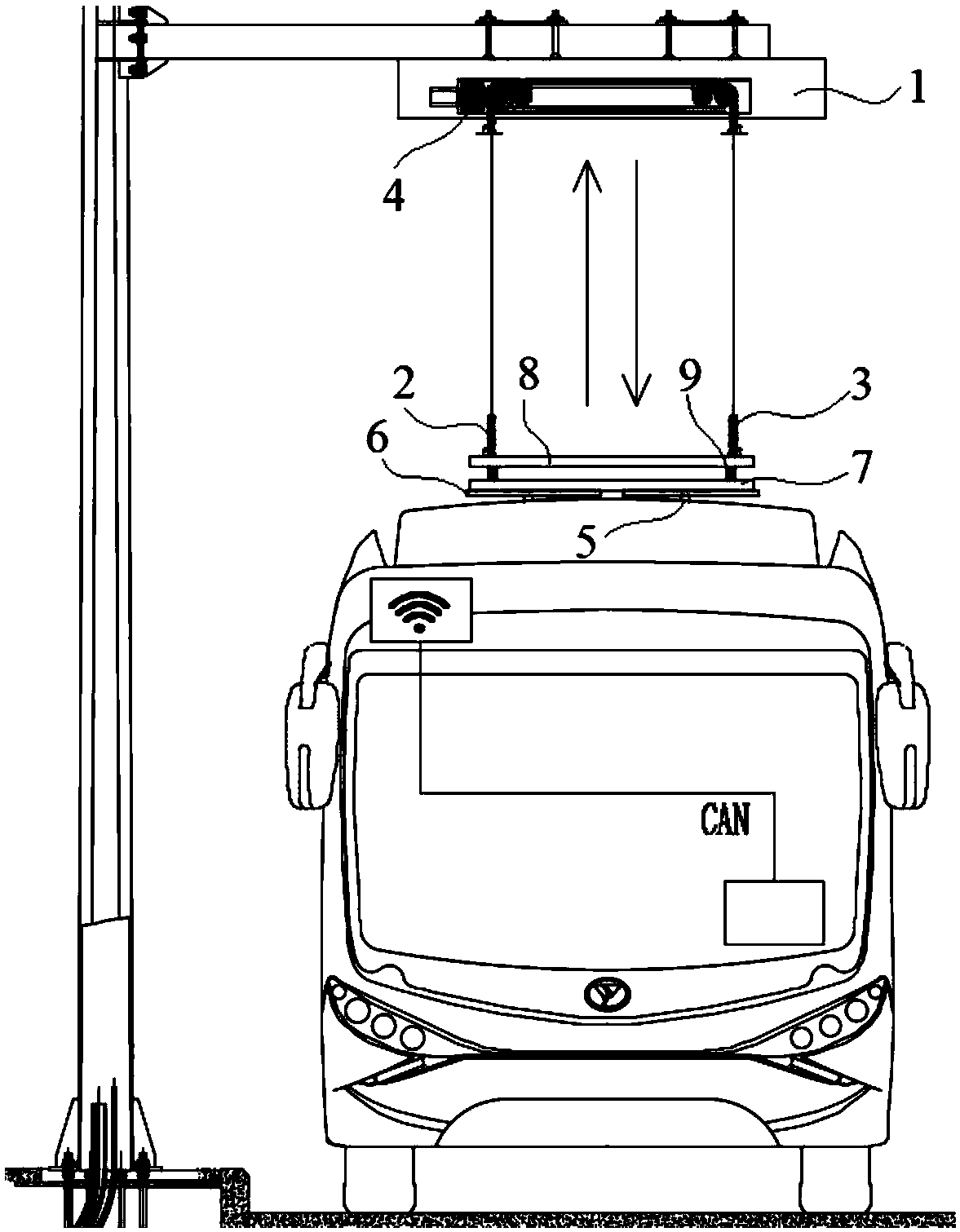
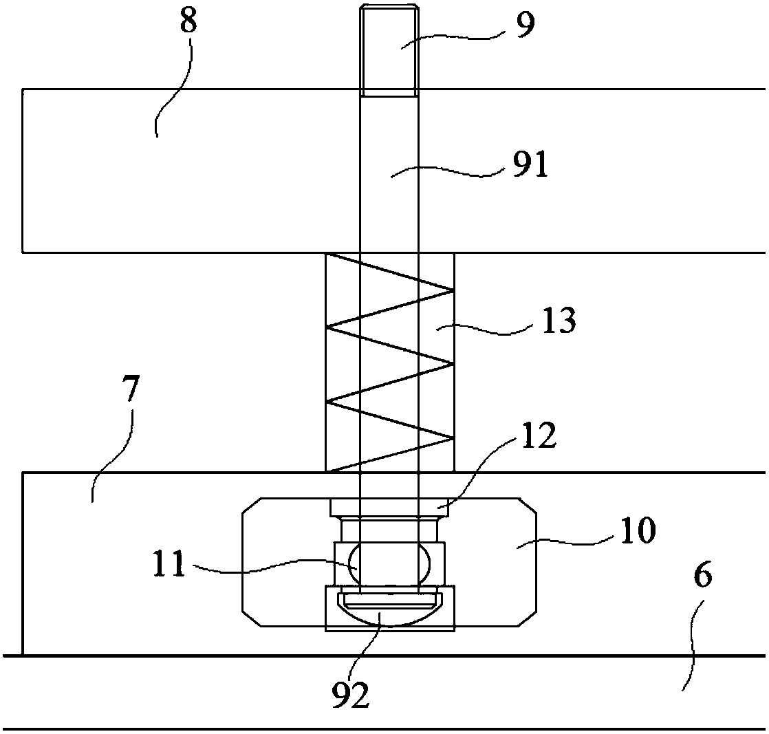
[0027] Embodiment 1: A charging device for a high-power group charging system, including a chain warehouse 1, a left support chain 2 and a right support chain 3 arranged in the chain warehouse 1, a support chain drive mechanism 4 and an electrode for receiving the vehicle roof. The charging pole 6 in contact with 5, the supporting chain driving mechanism 4 is located in the chain warehouse 1 and connected with the upper ends of the left supporting chain 2 and the right supporting chain 3 respectively, and is used to drive the left supporting chain 2 and the right supporting chain 3 to move up and down. The lower ends of the left support chain 2 and the right support chain 3 are installed and connected to the charging pole 6, and the charging pole 6 is connected to the left support chain 2 and the right support chain 3 through a mounting plate 7;

[0028]The lower ends of the left support chain 2 and the right support chain 3 are respectively fixedly connected with a fixed plate...

Embodiment 2

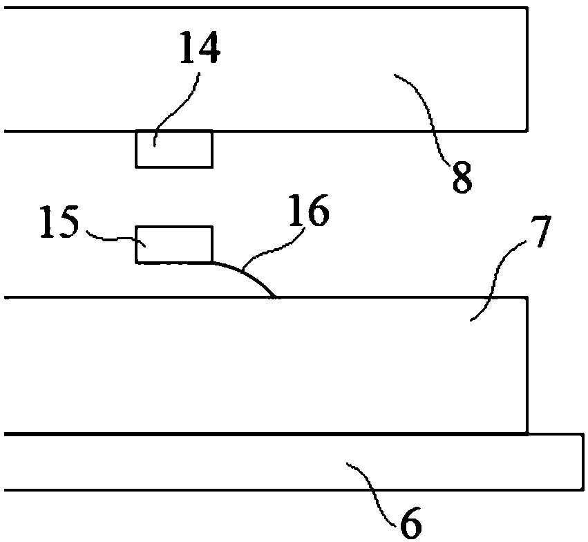
[0031] Embodiment 2: A charging device for a high-power group charging system, including a chain warehouse 1, a left support chain 2 and a right support chain 3 arranged in the chain warehouse 1, a support chain drive mechanism 4 and an electrode for receiving the vehicle roof. The charging pole 6 in contact with 5, the supporting chain driving mechanism 4 is located in the chain warehouse 1 and connected with the upper ends of the left supporting chain 2 and the right supporting chain 3 respectively, and is used to drive the left supporting chain 2 and the right supporting chain 3 to move up and down. The lower ends of the left support chain 2 and the right support chain 3 are installed and connected to the charging pole 6, and the charging pole 6 is connected to the left support chain 2 and the right support chain 3 through a mounting plate 7;

[0032] The lower ends of the left support chain 2 and the right support chain 3 are respectively fixedly connected with a fixed plat...


PUM


Abstract

The invention discloses a charging device for a high-power group charging system. The charging device includes a chain bin, a left support chain, a right support chain, a support chain driving mechanism and a charging pole for being in contact with a receiving electrode of a car roof, wherein the left support chain and the right support chain are arranged in the chain bin, a magnet is connected with a mounting plate through an elastic piece, the support chain driving mechanism further includes a driving motor mounted at one end of the chain bin, a driving gear connected with an output shaft ofthe driving motor, a first transmission gear connected with the driving gear, a second transmission gear connected with the first transmission gear through a transmission chain, a driven gear engagedwith the driving gear, and a left driven wheel and a left chain wheel which are connected through the left support chain, and the driving gear and the driven gear are mounted on the surface of the outer side of a first hanging plate or a second hanging plate opposite to the first transmission gear. According to the charging device for the high-power group charging system, the fully stable surfacecontact between the charging pole and the receiving electrode can be realized to ensure the charging efficiency, and the electrode contact strength can further be adjusted to be suitable for electricvehicles with various heights.

Description

technical field [0001] The invention relates to a charging device for electric vehicles, in particular to a charging device for a high-power group charging system, which belongs to the field of charging electric vehicles. Background technique [0002] The automobile industry is the second largest industry after petrochemical industry in the world. At present, most automobiles use gasoline and diesel as fuel, which not only consumes a large amount of oil resources, but also the nitrogen oxides and hydrocarbons contained in automobile exhaust pollutants, carbon monoxide, etc. have caused serious air pollution. In order to maintain the sustainable development of the national economy, protect the human living environment and ensure energy supply, governments around the world have invested a lot of manpower and material resources to find various ways to solve these problems. [0003] At present, there are mainly two ways to save energy, one is hybrid vehicles represented by Toyo...

Claims


Application Information

Patent Timeline
Patent Type & Authority Applications(China)
IPC IPC(8): B60L53/16H01R13/62H01R13/629H01R13/66
CPCH01R13/6205H01R13/629H01R13/6683H01R2201/26B60L53/14Y02T10/70Y02T90/14Y02T10/7072
Inventor 孙明常菊民吴永德
Owner SUZHOU IND PARK HESHUN ELECTRIC CO LTD
Why Eureka
Try Eureka