Evaporation source cleaning equipment and evaporation system

A technology for cleaning equipment and evaporation sources, applied in vacuum evaporation plating, sputtering plating, ion implantation plating, etc., can solve problems such as affecting the utilization rate of the evaporation system and the long baking process.

Active Publication Date: 2020-09-08
KUNSHAN GO VISIONOX OPTO ELECTRONICS CO LTD
View PDF5 Cites 0 Cited by
  • Summary
  • Abstract
  • Description
  • Claims
  • Application Information

AI Technical Summary

Problems solved by technology

The baking process takes a long time and directly affects the utilization rate of the evaporation system

Method used


Image

  • Evaporation source cleaning equipment and evaporation system
  • Evaporation source cleaning equipment and evaporation system
  • Evaporation source cleaning equipment and evaporation system

Examples


Embodiment Construction

[0022] Features and exemplary embodiments of various aspects of the invention will be described in detail below. In the following detailed description, numerous specific details are set forth in order to provide a thorough understanding of the present invention. It will be apparent, however, to one skilled in the art that the present invention may be practiced without some of these specific details. The following description of the embodiments is only to provide a better understanding of the present invention by showing examples of the present invention. In the drawings and the following description, at least some well-known structures and techniques have not been shown in order to avoid unnecessarily obscuring the present invention; and, for clarity, the dimensions of some structures may have been exaggerated. Furthermore, the features, structures, or characteristics described hereinafter may be combined in any suitable manner in one or more embodiments.

[0023] The orient...


PUM


Abstract

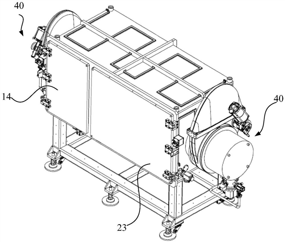
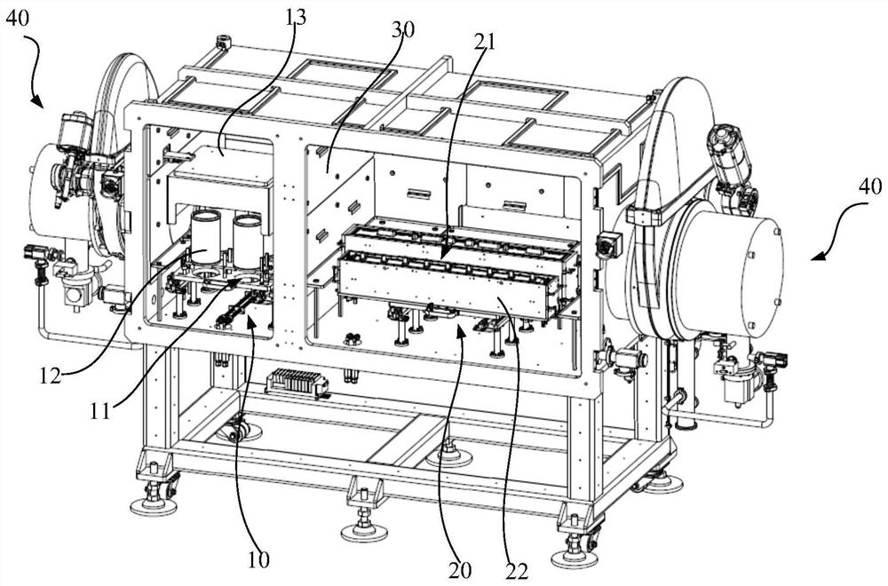
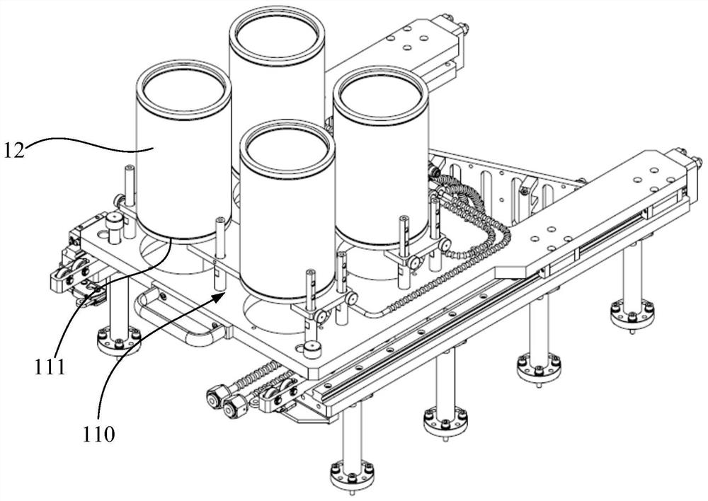
Disclosed is a vapor deposition source cleaning device, comprising: a vacuum chamber; a first vapor deposition source heating unit (11) arranged in the vacuum chamber, wherein the first vapor deposition source heating unit (11) comprises a support part (110), the support part (110) is used for the placing of at least one punctiform vapor deposition source, and the first vapor deposition source heating unit (11) is capable of providing thermal radiation for cleaning the punctiform vapor deposition source; and a second vapor deposition source heating unit (21) arranged in the vacuum chamber and spaced apart from the first vapor deposition source heating unit (11), wherein the second vapor deposition source heating unit (21) comprises at least one accommodating groove (211) used for the placing of a linear vapor deposition source or a planar vapor deposition source, and the accommodating groove (211) is capable of providing thermal radiation for cleaning the linear vapor deposition source or the planar vapor deposition source placed in the accommodating groove. Further disclosed is a vapor deposition system.

Description

technical field [0001] The invention belongs to the field of display technology, and in particular relates to an evaporation source cleaning device and an evaporation system. Background technique [0002] Organic Light Emitting Diode (OLED) display has the advantages of low cost, wide viewing angle, low driving voltage, fast response, rich luminous color, simple preparation process, and large-area flexible display. It is considered to be the most developed One of the foreground display technologies. [0003] The evaporation process of the OLED array substrate is usually carried out in the evaporation chamber of the evaporation equipment. During the evaporation process, the evaporation material will remain on the heater and the crucible, and it needs to be baked (baking) in the evaporation chamber regularly. ) to remove impurities remaining on the inner wall of the heater and crucible used in evaporation. The long baking process directly affects the utilization rate of the ...

Claims


Application Information

Patent Timeline
Patent Type & Authority Patents(China)
IPC IPC(8): C23C14/24C23C14/26
CPCC23C14/243C23C14/26
Inventor 方刚陈策王宝友尹俊
Owner KUNSHAN GO VISIONOX OPTO ELECTRONICS CO LTD
Why Eureka
Try Eureka