Electronic equipment analog signal calibration circuit

An analog signal and calibration circuit technology, which is applied in the field of circuits, can solve problems such as easy attenuation of signals, affecting the use effect of low-voltage electronic equipment, and large errors in analog signals.

Pending Publication Date: 2019-07-16
WUXI CITY COLLEGE OF VOCATIONAL TECH
View PDF0 Cites 13 Cited by
  • Summary
  • Abstract
  • Description
  • Claims
  • Application Information

AI Technical Summary

Problems solved by technology

[0002] At present, with the continuous development of science and technology, there are more and more electronic equipment, which greatly improves people's quality of life and level. Then, the most feedback on low-voltage electronic equipment is that the analog signal received by the control ...

Method used


Image

  • Electronic equipment analog signal calibration circuit
  • Electronic equipment analog signal calibration circuit

Examples


Embodiment 1

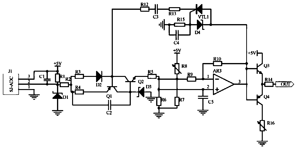
[0012] Embodiment 1, an analog signal calibration circuit for electronic equipment, including a frequency acquisition circuit, a feedback constant current circuit and a push-pull output circuit, the frequency acquisition circuit collects the signal frequency in the analog signal channel of the low-voltage electronic equipment control terminal, the analog signal channel It is the channel for the output signal of the low-voltage electronic equipment control terminal to receive the signal acquisition module. The feedback constant current circuit uses the triode Q1, the triode Q2 and the voltage regulator tube D3 to form a constant current source circuit to stabilize the signal potential. At the same time, the variable resistor R8 and the operational amplifier are used. AR3 forms a current-voltage conversion circuit to convert the current signal into a voltage signal and then input it into the push-pull output circuit. The abnormal signal detection circuit is composed of the thyrist...

Embodiment 2

[0014] Embodiment 2. On the basis of Embodiment 1, the push-pull output circuit uses triode Q3, triode Q4 and variable resistor R16 to form a push-pull circuit to reduce the signal conduction loss and then output, which is to simulate the low-voltage electronic equipment control terminal. The compensation signal of the signal in the signal channel adopts the method of signal compensation to prevent insufficient signal power and ensure the stability of signal transmission. The base of the transistor Q3 is connected to the base of the transistor Q4 and the output terminal of the operational amplifier AR3, and the collector of the transistor Q3 The electrode is connected to the power supply +5V, the emitter of the transistor Q3 is connected to one end of the resistor R14 and the emitter of the transistor Q4, the collector of the transistor Q4 is connected to one end of the variable resistor R16, the other end of the variable resistor R16 is grounded, and the other end of the resist...

Embodiment 3

[0015] Embodiment 3. On the basis of Embodiment 1, the frequency acquisition circuit selects the frequency transformer J1 of the model SJ-ADC to collect the signal frequency in the analog signal channel in the control terminal of the low-voltage electronic equipment, and the voltage regulator D1 stabilizes the voltage, and the frequency mutual inductance The power supply terminal of the transformer J1 is connected with the capacitor C1, one end of the resistor R1 and the power supply +5V, the ground terminal of the frequency transformer J1 is grounded, and the output terminal of the frequency transformer J1 is connected with the capacitor C1, the other end of the resistor R1, one end of the resistor R2 and the stabilizer The negative pole of the pressure tube D1, the other end of the resistor R2 is connected to the other end of the resistor R3, and the positive pole of the regulator tube D1 is grounded.

[0016] When the present invention is used specifically, an electronic dev...


PUM


Abstract

The invention discloses an electronic equipment analog signal calibration circuit. The circuit comprises a frequency acquisition circuit, a feedback constant current circuit and a push-pull output circuit. The frequency acquisition circuit acquires signal frequency in an analog signal channel in the low-voltage electronic equipment control terminal; the feedback constant current circuit utilizes atriode Q1, a triode Q2 and a voltage stabilizing tube D3 to form a constant current source circuit stable signal potential. Meanwhile, a current-voltage conversion circuit composed of a variable resistor R8 and an operational amplifier AR3 is used for converting a current signal into a voltage signal and inputting the voltage signal into a push-pull output circuit; an abnormal signal detection circuit is composed of a silicon controlled rectifier VTL1 and a voltage-regulator tube D4 and feeds back abnormal signals to the collector electrode of a triode Q2. and finally, the push-pull output circuit uses a triode Q3, a triode Q4 and a variable resistor R16 to form a push-pull circuit to reduce signal conduction loss and then output the signal, so that the signal frequency can be converted into a compensation signal of a signal in an analog signal channel in a remote intelligent equipment control terminal.

Description

technical field [0001] The invention relates to the technical field of circuits, in particular to an analog signal calibration circuit for electronic equipment. Background technique [0002] At present, with the continuous development of science and technology, there are more and more electronic equipment, which greatly improves people's quality of life and level. Then, the most feedback on low-voltage electronic equipment is that the analog signal received by the control terminal has a large error, that is, the factory The signal in the analog signal channel of the low-voltage electronic equipment control terminal is prone to attenuation during transmission, resulting in insufficient signal power, which seriously affects the use of low-voltage electronic equipment. Contents of the invention [0003] In view of the above situation, in order to overcome the defects of the prior art, the object of the present invention is to provide an electronic equipment analog signal cali...

Claims


Application Information

Patent Timeline
IPC IPC(8): H03K19/003
CPCH03K19/00307
Inventor 孔得丰
Owner WUXI CITY COLLEGE OF VOCATIONAL TECH
Why Eureka
Try Eureka